Chapter 6: Database Design Using the ER Model
In this chapter, we focus on conceptual design.
Overview of Design Process
Design process consists of two phases:
- Analyzing of requirements
- What data should be stored
- What operations/transaction are conducted such as insert, delete, and update
- Designing of DB schemas, with the three-level data abstract
- conceptual design
- logical design
- physical design
flowchart TD
    A[Application problems in real words] -->|Requirements analysis| B[Specification of user requirements]
    B -->|<span style="color:red;">Conceptual DB design</span>| C[DB conceptual schema, i.e. ER diagram]
    C -->|Logical DB design| D[DB logical schema, i.e. relational data schema]
    D -->|Physical DB design| E[DB physical schema, e.g. physical storage structure]
The lifecycle of Database Application System (DBAS) design consists of five phases: project planning, requirements analysis, system design, implementation and deployment, and operation management and maintenance.
Based on the composition and functionality of the software, the design is divided into three main lines: data organization and storage design, data access and processing design, and application design, which corresponds to the design of the database, database transactions, and applications, respectively.
According to the three-level schema structure of the database system, the design phase is divided into three steps: conceptual design, logical design, and physical design.
The Entity-Relationship Model
ER Model employs three concepts: entity sets, relationship sets, and attributes. ER model has an associated diagrammatic representation, the ER diagram, expressing the overall logical structure of DB graphically.
Entity Sets
Def. An entity is an object that exists distinguishable from other objects. e.g. a specific person.
Def. An entity set is a set of entities of the same type, sharing the same properties. e.g. group of persons
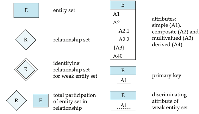
Note: an entity is represented by a set of attributes (descriptive properties of an entity set).
Def. A subset of the attributes form a primary key
Note: an entity consists of all values of its all attributes.
Relationship Sets
Def. A relationship is an association among several entities.
Def. A relationship set is a mathematic relation among \(n\) entities (\(n \geq 2\)) taken from entity sets \(\{(e_1, e_2, \cdots, e_n) \mid e_1 \in E_1, \cdots, e_n \in E_n\}\)
Def. A relationship instance represents an association between the named entities in the real-word enterprise.
Def. An attribute can also be associated with a relationship set.
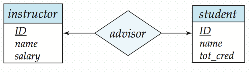
For example, the advisor relationship set between instructor and student has an attribute date when student started being associated with the advisor
Def. A role of entity is a function that an entity plays in a relationship.
Note: entity sets of a relationship need not be distinct.
Def. Binary relationship involves two entity sets (degree two)
Complex Attributes
Def. The domain or values set of the attribute is the set of permitted values.
Attribute types:
- simple and composite attributes
- single-valued and multi-valued attributes
- derived attributes (can be computed from other attributes, e.g. age, given date_of_birth)
Null value for a attribute means
- the attribute not applicable for the entity, not existing
- the value for the attribute exists, but is unknown
Composite attributes allow us to divide attributes into subparts. For example
flowchart TD
    A[name] --> B[first_name]
    A --> C[middle_name]
    A --> D[last_name]
Redundant Attributes
Suppose we have entity sets:
- instructor, with attributes: ID, name, dept_name, salary
- department, with attributes: dept_name, building, budget
Model: each instructor is in a department using relationship set inst_dept.
The attribute dept_name appears in both entity sets. Since it is the primary key for the entity set department, it replicates information present in the relationship. It is therefore redundant in the entity set instructor.
Mapping Cardinalities Constraints
- Semantic constraints, as integrity constraints, to maintain consistency
- Integrity constraints on E or R
- Mapping cardinalities
- Participation constraints
- Cardinality limits
- Keys
Mapping Cardinalities
Def. Mapping Cardinalities are the number of entities to which another entity can be associated via a relationship set.
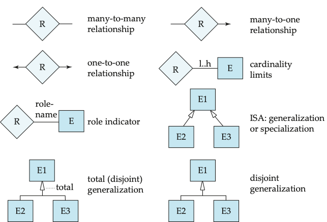
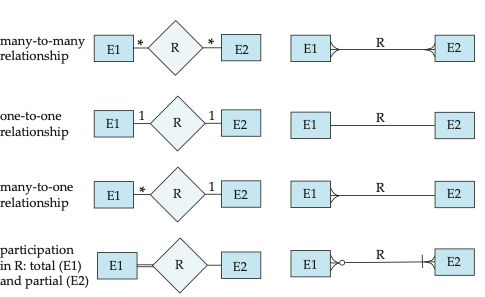
Def. For a binary relationship set \(R\), from \(A\) to \(B\), the mapping cardinality must be: one to one, one to many, many to one, and many to many.
One to One
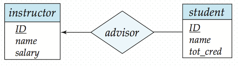
A student is associated with at most one instructor via the relationship advisor.
One to Many
An instructor is associated with several (including \(0\)) students via advisor. A student is associated with at most one instructor via advisor.
Participate Constraints
Def. The participation of an entity \(E\) in a relationship \(R\) is total, if every entity in \(E\) participates in at least one relationship in \(R\).
Def. The participation of an entity \(E\) in a relationship \(R\) is partial, if some entities in \(E\) may not participate in any relationship in \(R\).
Cardinality Limits for Participation
Def. Cardinality limits express quantitative constraints on participation.
Explicit, recommended!
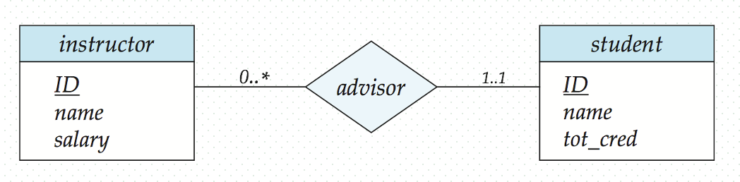
A maximum value * indicates no limit
Primary Keys
Def. Key is a set of attributes (from an entity set or a relationship set). The values of these attributes in one entity to uniquely distinguish this entity from others and the values of these attributes in one relationship to uniquely identify the relationship.
Keys for Entity Set
Def. A super key of an entity set is a set of one or more attributes, whose values uniquely determine each entity in the entity set. The super key may contain extraneous attributes.
Def. A candidate key is the minimal super key (non-redundant super key).
Def. The primary key is a candidate key chosen as the principal means of identifying entities within an entity set. Although several candidate keys may exists, one of the candidate keys is selected to be the primary key.
Keys for Relationship Sets
Def. Keys for relationship sets \(R\) on entities \(E_1\), \(E_2\), \(\cdots\), \(E_n\), uniquely distinguish each relationship instances.
Def. The super keys for \(R =\) \(E_1\)’s primary key \(\cup \cdots \cup E_n\)’s primary key.
Note: if the attribute names of primary keys are not unique, the attributes with the same names should be renamed.
Def. The candidate keys for \(R\) (minimal, non-redundant super keys).
Choice of Primary Key for Binary Relationship
The candidate keys or primary key for \(R\) among entity sets \(A\) amd \(B\) can be decided, in accordance with the mapping cardinality of \(R\), as follows
- If \(R\) is many to many, \(R\)’s primary key \(=\) \(A\)’s primary key \(\cup\) \(B\)’s primary key
- If \(R\) is many to one from \(A\) to \(B\), \(R\)’s primary key \(=\) \(A\)’s primary key (many side)
- If \(R\) is one to one, \(R\)’s primary key \(=\) \(A\)’s primary key or \(B\)’s primary key
Weak Entity Sets
Def. An entity set that does not have a primary key is a weak entity set
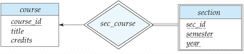
Consider section entity set, identified by course_id, semester, year, sec_id. Entities in section are related to entities in course.
- Suppose a relationship set sec_course between entity sets section and course
- The information in sec_course is redundant, since section already has attribute course_id, which identifies the course with which the section is related
- To deal with redundancy is to get rid of the relationship sec_course; however, relationship between section and course becomes implicit
We can introduce weak entity set
- Not store the attribute course_id in the section entity, but only store the remaining attributes section_id, year, and semester
- However, the entity set section does not have enough attributes to identify a particular section entity uniquely
- To deal with this problem, we treat relationship sec_course as a special relationship that provides extra information (section is modeled as a weak entity set).
Def. A weak entity set called identifying entity is one, whose existence is dependent on another entity.
Def. Identifying relationship is the relationship associating the weak entity set with the identifying entity set.
A weak entity set is depicted via a double rectangle. Underline the discriminator of a weak entity set with a dashed line. The relationship set connecting weak entity set to identifying string entity set is depicted by a double diamond
Def. The discriminator (or partial key) of a weak entity set is the set of attributes that distinguishes among all those entities in weak entity set that depending on a particular strong entity.
Note: use identifying entity, along with extra attributes called discriminator to uniquely identify a weak entity, instead of a primary key.
Every weak entity must be associated with an identifying entity; weak entity set is existence dependent on identifying entity set.
Removing Redundant Attributes
Suppose we have entity sets:
- student, with attributes: ID, name, tot_cred, dept_name
- department, with attributes: dept_name, building, budget
- Each student has an associated department using a relation set stud_dept
The attribute dept_name in student replicates information present in relationship. It is redundant and needs to be removed. But when converting back to tables, the attribute should be reintroduced.
Reducing ER Diagrams to Relation Schemas
Logical database design with steps: generation of initial relational schema from the ER diagram, and normalization of relational schema. Converting an ER diagram to a table format is the basis for deriving a relational database design (conceptual design to logical design).
A database which conforms to an ER diagram can be represented by a collection of schemas/tables
- Entity sets and relationship sets can be expressed uniformly as relation schemas that represent the contents of the database
- there is a unique schema corresponding to either entity set or relationship set
- Each table has a number of columns, corresponding to their attributes
A strong entity set reduces to a schema with the same attributes; a weak entity set becomes a table that includes a column for the primary key of the identifying strong entity set
Composite attributes are flattened by separate attributes.
Representing Relationship Sets
Reduction of a relationship set into tables are strongly dependent on the mapping cardinality constraint and total/partial constraints.
- A many to many relationship sets is represented as an independent table with columns for the primary keys of two participating entity sets, and any descriptive attributes of the relationship set
- Many to one and one to many relationship sets that total on the many side can be represented by adding an extra attribute (the primary key of the one side) to the many side.
- Many to one relationship sets with partial participation on the many side. The relationship is reduced to an independent table, avoiding null values
- For one to one relationship sets, either side can be chosen to act as the many side
Extended ER Features
- Specialization
- Top-down design process
- We designate sub-groupings within an entity set that are distinctive from other entities
- These sub-groupings become lower-level entity sets that have attributes or participate in relationships that do apply to the higher-level entity set
- Depicted by a triangle component labeled ISA
- Attribute inheritance
- A lower-level entity set inherits all the attributes and relationship participation of the higher-level entity set to which it is linked
- A higher-level entity’s attributes and relationship can apply to all of its lower-level entities
- Generalization
- Bottom-up design process
- Combine a number of entity sets that share the same features into a higher-level entity set
- Bottom-up design process
Specialization and generalization are simple inversion of each other. They are represented in an ER diagram in the same way. The terms specialization and generalization are used interchangeably.
Superclass and Subclass
The ISA relationship, or containment, is also referred to as superclass-subclass relationship.
For the entity sets \(A\) and \(B\), if \(A\) is the generalization of \(B\), then \(A\) is the superclass of \(B\), and \(B\) is the subclass of \(A\).
Completeness Constraint
Completeness constraint specifies whether or not an entity in the higher-level entity set must belong to at least one of the lower-level entity sets within a generalization.
- Total: an entity must belong to one of the lower-level entity sets
- Partial: an entity need not belong to one of the lower-level entity sets
We can specify total generalization by adding the keyword total in the diagram and drawing a dashed line from the keyword to the corresponding hollow arrow-head (for a total generalization), or to the set of hollow arrow-heads (for an overlapping generalization).
What’s more, constraints on whether or not a higher-level entity may belong to more than one lower-level entity set within a single specialization
- Disjoint: a higher-level entity can belong to only one lower-level entity set
- Overlapping: a higher-level entity can belong to more than one lower-level entity sets
Representing Specialization via Schemas
- Method 1
- Form a schema for the higher-level entity
- Form a schema for each lower-level entity set, including primary key of higher-level entity set and local attributes.
- Method 2
- Form a schema for each entity set with all local and inherited attributes
- Method 3
- If specialization is disjoint and total, creating two tables
- \(T_1(a_1, a_2, \cdots, a_m, c_1, c_2, \cdots, c_k, d_1, d_2, \cdots, d_j)\)
- \(T_2(b_1, b_2, \cdots, b_n, c_1, c_2, \cdots, c_k, d_1, d_2, \cdots, d_j)\)
- \(a_1\), \(a_2\), \(\cdots\), \(a_m\) are attributes of one lower-level entity set, \(b_1\), \(b_2\), \(\cdots\), \(b_n\) are attributes of the other lower-level entity set, and \(c_1\), \(c_2\), \(\cdots\), \(c_k\), \(d_1\), \(d_2\), \(\cdots\), \(d_j\) are all attributes of higher-level entity set.
ER Design Issues
- Not to use the primary key of an entity set as an attribute of another entity set (to represent implicitly association between two entity sets), it is better to use an relationship set to explicitly show this association.
- If \(E\) participate in \(R\), not to designate the primary key (\(E\)) as attributes of \(R\), to avoid information redundancy
- Possible guideline is to designate a relationship set to describe an action that occurs between entities
- Prefer to using the binary relationship set, replace a non-binary relationship set by a number of binary relationship set
Converting Non-Binary Relationships to Binary Form
In general, any non-binary relationship can be represented using binary relationships by creating an artificial entity set \(E\).
For example, a 3-ary relationship set \(R = \{(a_i, b_i, c_i) \mid a_i \in A, b_i \in B, c_i \in C\}\) among entity sets \(A\), \(B\), \(C\), replace \(R\) by an entity set \(E = \{e_{i}\}\), and three binary relationship set \(R_a\), \(R_b\), \(R_c\).
- \(E = \{e_i\}\), \(|E| = |R|\), i.e. each \((a_i, b_i, c_i)\) in \(R\) corresponds to one \(e_i\) in \(E\)
- \(R_a = \{(e_i, a_i) \mid e_i \in E, a_i \in A\}\), relating \(E\) and \(A\)
- \(R_b = \{(e_i, b_i) \mid e_i \in E, a_i \in B\}\), relating \(E\) and \(B\)
- \(R_c = \{(e_i, c_i) \mid e_i \in E, a_i \in C\}\), relating \(E\) and \(C\)
- \(E\) has an identifying attribute \(e\) (candidate key) to distinguish each \(e_i\) in \(E\)
- All attributes of \(R\) are assigned to \(E\).
Summary of Symbols Used in ER Notation

例题
A database used in an ordering system contains information about customers, products, and orders. The following information is to be included:
- for each customer
- customer number, ship to address (several per customer), name, balance, discount
- for each order
- order number, customer number, ship to address (one per order), date of ordering (including year, month, and day), products (several kinds per order), quantity ordered of each_product
- for each kind of product
- product number, name, manufacturing plant, quantity on hand
- entity sets: customer, order, product, and their attribute
- in customer, ship to address is a multi-value attribute, but in order, ship to address is a single-value attribute
- in order, date is a composite attribute
Some constraints about this ordering system are as follows
- a customer may take one or more orders, and some customers may take no orders
- each order must be for one (and only one) customer
- each order must contain at least one kind of products
- a kind of product may appear in several orders, but some kinds of products may not be ordered by any customers
- relationship sets
- make between customer and order
- customer partly participates make, and order totally participates make
- in relationship set make, mapping cardinality from customer to order is one to many
- contain between order and product, and descriptive attributes quantity of ordered for relationship set contain
- product partly participates contain, and order totally participates contain
- in relationship set contain, mapping cardinality from order to product is many to many
- make between customer and order
ER diagram of the ordering DB is shown as follows:
The ER diagram is then reduced to some relational tables. For entity set customer and its multi-value attribute ship to address, there are two tables
- customer(C-number, c-name, discount, balance)
- ship-to-address(C-number, ship-to-address)
For entity set order and its composite attribute date which should be decomposed, there is a table
- order1(O-number, ship-to-address, year, month, day)
For entity set product, there is a table
- product(P-number, p-name, plant, quantity-on-hand)
For relationship set make, there no descriptive attributes, mapping cardinality from customer to order is one to many, and order totally participates make. So, make should not be reduced into a separate table, and can be represented by adding the primary key C-number of customer, that is C-number into the table order
- order2(O-number, C-number, ship-to-address, year, month, day)
product at the many side only partly participate relationship set contain, contain should also be represented as a separate table
- contain(O-number, P-number, quantity of ordered)