IO Devices and Disk
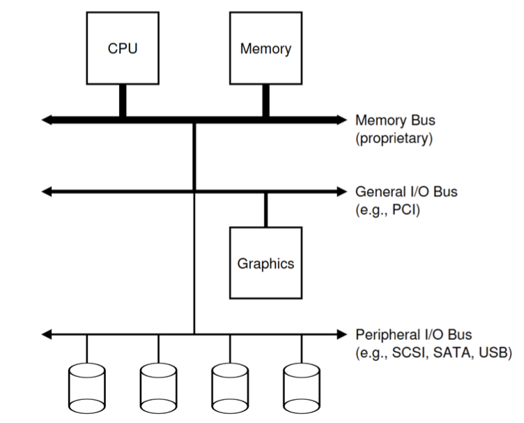
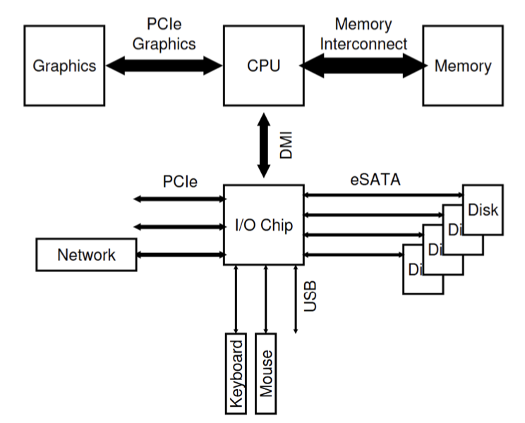
I/O Devices
A simple IO device should have two parts:
- Interface.
- Internal structure.
- Implementation specific and is responsible for implementing the abstraction the device presents to the system.
- Complex devices could have their own CPU and memory as well.
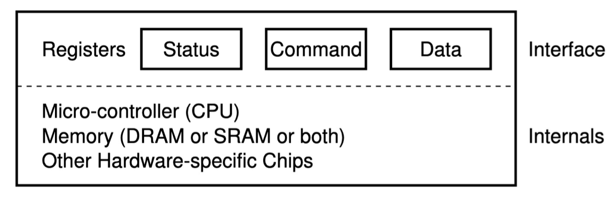
- A status register, which can be read to see the current status of the device;
- A command register, to tell the device to perform a certain task;
- A data register to pass data to the device, or get data from the device.
An example code may be like:
2While (STATUS == BUSY)
; // wait until device is not busyBut polling is inefficient. We use interrupts instead of polling.
Direct Memory Access
A DMA engine is a very specific device that can orchestrate transfers between devices and main memory without much CPU intervention.
To transfer data to the device, for example, the OS would program the DMA engine by telling it where the data lives in memory, how much data to copy, and which device to send it to. At that point, the OS is done with the transfer and can proceed with other work.When the DMA is complete, the DMA controller raises an interrupt, and the OS thus knows the transfer is complete.
There are two complementary ways for CPU to access I/O devices.
I/O devices have their own registers (or memory).
- Memory-mapped I/O (MMIO): let memory and devices share the physical address space
- Most widely adopted.
- Shared address bus.
- Port-mapped I/O (PMIO), or isolated I/O: use specialized instructions to R/W I/O devices.
- In Intel: outb, outw, etc.
Storage Devices
Second storage:
- Magnetic disk: hard disk, floppy disk, etc.
- Optical disk: CD, DVD, blu-ray, etc.
- Flash memory: pen drive, SD card, etc.
Storage devices:
- Magnetic disks
- Storage that rarely becomes corrupted.
- Large capacity at low cost.
- Block level random access.
- Slow performance for random access.
- Better performance for sequential access.
- Flash memory
- Storage that rarely becomes corrupted.
- Capacity at intermediate cos (5 - 20x disk).
- Block level random access.
- Good performance for reads; worse for random writes.
- Erasure requirement in large blocks.
- Wear patterns issue.
The Magnetic Disk
- Sector: the unit of transfer.
- Track: ring of sectors
- ~ \(1\) um (\(10^{-6}\) m) wide.
- Resolution of human eye: \(50\) um
- Wavelength of lights is ~ \(0.5\) um.
- ~ \(1\) um (\(10^{-6}\) m) wide.
- Cylinder: attached to movable arms to read data.
- \(2\) per each platter for each surface.
- Storage capacity \(=\) (head #) \(\times\) (cylinder #) \(\times\) (sector #) \(\times\) (sector size)
- Often \(512\) bytes.
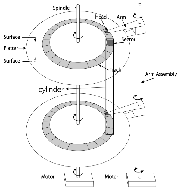
Cylinders: all the tracks under the head at a given point on all surface.
Read/write data is a three-stage process:
- Seek time: position the head/arm over the proper track.
- Rotation latency: wait for desired sector to rotate under r/w head.
- Transfer time: transfer a block of bits (sector) under r/w head.
Disk latency \(=\) queuing time + controller time + seek time + rotation time + transfer time.
Request \(\to\) Software Queue \(\to\) Hardware Controller \(\to\) Media Time \(\to\) Result
Here is a disk performance example. We assume that
- Ignoring queuing and controller times for now.
- Avg seek time of \(5\) ms.
- \(7200\) RPM \(\Rightarrow\) time for rotation: \(60000\) (ms/min) / \(7200\) (rev/min) \(\approx\) \(8\) ms.
- Transfer rate of \(4\) MByte/s, sector size of \(1\) KByte \(\rightarrow\) \(1024\) bytes / \(4 \times 10^6\) (bytes/s) \(= 256 \times 10^{-6}\) sec \(\approx 0.26\) ms.
Read sector from random place on disk:
- Seek (\(5\) ms) + Rot.Delay (\(4\) ms) + Transfer (\(0.26\) ms) \(= 9.26\) ms.
- Approx \(10\) ms to fetch/put data: \(100\) KByte/sec.
Read sector from random place in same cylinder:
- Rot.Delay (\(4\) ms) + Transfer (\(0.26\) ms) \(= 4.26\) ms.
- Approx \(5\) ms to fetch/put data: \(200\) KByte/sec.
Read next sector on same track:
- Transfer (\(0.26\) ms): \(4\) MByte/sec.
Intelligence in the Controller
- Sectors contain sophisticated error correcting codes
- Disk head magnet has a field wider than track.
- Hide corruptions due to neighboring track writes.
- Sector sparing
- Remap bad sectors transparently to spare sectors on the same surface.
- Slip sparing
- Remap all sectors (when there is a bad sector) to preserve sequential behavior.
- Track skewing
- Sector numbers offset from one track to the next, to allow for disk head movement for sequential ops.
Solid State Disks (SSDs)
1995 – Replace magnetic media with non-volatile memory (battery backed DRAM)
2009 – Use NAND Multi-Level Cell (2 or 3-bit/cell) flash memory
- Sector (4 KB page) addressable, but stores 4-64 ”pages” per memory block.
- Trapped electrons distinguish between 1 and 0.
No moving parts (no rotate/seek motors)
- Eliminates seek and rotational delay (0.1-0.2ms access time)
- Very low power and lightweight
- Limited “write cycles”
Rapid advances in capacity and cost ever since!
SSD architecture
- Read \(4\) KB page: \(\sim 25\) \(\mu\)s
- No seek or rotational latency.
- Transfer time: transfer a \(4\) KB page
- SATA: \(300\) - \(600\) MB/s \(\Rightarrow \sim 4 \times 10^3\) b / \(400 \times 10^6\) bps \(\Rightarrow 10\) \(\mu\)s
- Writing data is complex (\(\sim 200\) \(\mu\)s - \(1.7\) ms)
- Can only write empty pages in a block.
- Erasing a block takes \(\sim 1.5\) ms.
- Controller maintains pool of empty blocks by coalescing used pages (read, erase, write), also reserves some \(\%\) of capacity.
- Rule of thumb: writes \(10\)x reads, erasure \(10\)x writes
SSD summary:
- Pros (compared to hard disk drives):
- Low latency, high throughput (eliminate seek/rotational delay).
- No moving parts:
- Very light weight, low power, silent, very shock insensitive.
- Read at memory speeds (limited by controller and I/O bus)
- Cons
- Asymmetric block write performance: read pg/erase/write pg
- Controller garbage collection (GC) algorithms have major effect on performance
- Limited drive lifetime
- \(1\) - \(10\) K writes/page for MLC NAND
- Avg failure rate is \(6\) years, life expectancy is \(9\) – \(11\) years
- Asymmetric block write performance: read pg/erase/write pg
Disk Scheduling
Disk can do only one request at a time. What order do you choose to do queued requests?
The scheduling can be done in OS, firmware, or both.
- FIFO
- Fair among requesters, but order of arrival may be to random spots on the disk \(\Rightarrow\) Very long seeks.
- SSTF: shortest seek time first
- Pick the request that’s closest on the disk
- Although called SSTF, today must include rotational delay in calculation, since rotation can be as long as seek
- Con: SSTF good at reducing seeks, but may lead to starvation
- SCAN
- Implements an Elevator Algorithm: take the closest request in a fixed direction of travel (reversed at the end)
- No starvation, but retains flavor of SSTF
- C-SCAN: circular-scan
- Only goes in one direction
- Skips any requests on the way back
- Fairer than SCAN, not biased towards pages in middle
A simple read() lifecycle
- A process issues a syscall read()
- OS moves the calling thread to a wait queue (state=WAITING)
- OS uses memory-mapped I/O to tell the disk to read the requested data and set up DMA so the disk can place the data in kernel’s memory
- Disk reads the data and DMAs it into main memory
- Disk triggers an interrupt
- OS’s interrupt handler copies the data from the kernel’s buffer into the process’s address space
- OS moves the thread to the ready list
- The thread is scheduled on CPU, and returns from the read()
File System Abstraction
How files and directories are organized in memory and disk.
Def. File system is a layer of OS that transforms block interface of disks (or other block devices) into files, directories, etc.
File system components:
- Naming: interface to find files by name, not by blocks.
- Disk management: collecting disk blocks into files.
- Protection: layers to keep data secure.
- Reliability/Durability: keeping of files despite crashes, media failures, attacks, etc.
Disk Management Policies
- Basic entities on a disk:
- Files: user-visible group of blocks arranged sequentially in logical space.
- Directory: user-visible index mapping names to files.
- Access disks as linear array of sectors. Two options;
- Identify sectors as vectors [cylinder, surface, sector], sort in cylinder-major order
- Used in BIOS, but not in OSes anymore
- Logical Block Addressing: Every sector has integer address from zero up to max number of sectors
- Controller translates from address \(\Rightarrow\) physical position
- First case: OS/BIOS must deal with bad sectors
- Second case: hardware shields OS from structure of disk
- Identify sectors as vectors [cylinder, surface, sector], sort in cylinder-major order
- Need way to track free disk blocks
- Link free blocks together \(\Rightarrow\) too slow today
- Use bitmap to represent free space on disk
- Need way to structure files: file header
- Track which blocks belong at which offsets within the logical file str ucture
- Optimize placement of files’ disk blocks to match access and usage patterns
File
- Named permanent storage
- Contains
- Data
- Blocks on disk somewhere
- Metadata (attributes)
- Owner, size, last opened
- Access rights
- R, W, X
- Owner, group, other (in Unix systems)
- Access control list in Windows system.
- Data
Directory
- Basically a hierarchical structure
- Each directory entry is a collection of
- Files
- Directories
- A link to another entries
- Each has a name and attributes.
- Files have data
- Links (hard links) make it a DAG, not just a tree
- Softlinks (aliases) are another name for an entry.
- Conventions of directory
- Root directory: “/”
- Home directory: “~/cur_dir/file.txt”
- Absolute path: “/home/mwx/cur_dir/file.txt”
- Relative path: “file.txt”
- Volume: a collection of physical storage resources that form a logical storage device. Could be a part of or many physical devices.
- Mount: an operation that creates a mapping from some path in the existing file system to the root directory of the mounted volume’s file system
例题
(1). 在一个物理磁盘中,不考虑 queueing 和 controller 的时延,平均寻道时间为 \(3 \text{ms}\),磁盘转速为 \(10000 \text{RPM}\),I/O 读取速度为 \(8 \text{MB/s}\),扇区大小为 \(1 \text{KB}\)。请分别计算
- 平均延迟时间,注意,磁头只可以单向转动
- 完全随机读取速率,单位 KB/s,且不考虑调度器优化
- 完全顺序读取速率,单位 KB/s
转一圈的耗时为 \(\frac{60000 \text{ms/min}}{10000 \text{RPM}} = 6 \text{ms}\),读取时间为 \(\frac{1 \text{KB}}{8 \times 2^{10} \times 10^{-3} \text{KB/ms}} = 0.128 \text{ms}\)。
- 平均延迟时间为 \(3 \text{ms}\)
- 完全随机读取速率为 \(\frac{1 \text{KB}}{(3 + 3 + 0.128) \text{ms}} \approx 163 \text{KB/s}\)
- 完全顺序读取速率为 \(8 \text{MB/s}\)