The Data Link Layer
Notice !:
- Computer Networking_ A Top-Down Approach, Global Edition, 8th Edition for CONTENT
- Computer Networking_ A Top-Down Approach, Global Edition, 3th Edition for QUESTION
Introduction and Service
Some terminology
- Nodes: hosts and routers;
- Links: communication channels that connect adjacent nodes along communication path;
- wired links
- wireless links
- LANs
- layer-2 packet is a frame, encapsulates datagram.
Link layer: context
datagram transferred by different link protocols over different links, each link protocol provides different services.
Link Layer Services
- framing, link access
- encapsulate datagram into frame, adding header, trailer.
- channel access if shared medium.
- “MAC” addresses used in frame headers to identify source, dest.
- reliable delivery between adjacent nodes
- seldom used on low bit-error link (fiber, some twisted pair).
- flow control
- pacing between adjacent sending and receiving nodes.
- error detection
- errors caused by signal attenuation, noise.
- receiver detects presence of errors: signals sender for retransmission or drops frame.
- error correction
- receiver identifies and corrects bit error(s) without resorting to retransmission.
- half-duplex and full-duplex
- with half duplex, nodes at both ends of link can transmit, but not at same time.
Where is the link layer implemented?
- The link layer is implemented in every host.
- It is realized through an adaptor, also known as a Network Interface Card (NIC).
- Examples include: Ethernet cards, PCMCIA cards, and 802.11 wireless cards.
- The adaptor is responsible for implementing both the link layer and the physical layer.
- It connects to the host via the system buses.
- The adaptor is a combination of hardware, software, and firmware.
📌 In essence, the NIC handles the lower layers of network communication and serves as the interface between the host and the physical network.
Adaptors Communicating

Sending Side
- Encapsulates the network-layer datagram into a link-layer frame.
- Adds:
- Error checking bits (e.g., CRC).
- Reliable data transfer (rdt) mechanisms (if needed).
- Flow control to manage data rate between sender and receiver.
Receiving Side
- Checks the frame for:
- Errors using error detection codes.
- Reliable data transfer mechanisms.
- Flow control compliance.
- Extracts the datagram from the frame.
Error Detection and Correction
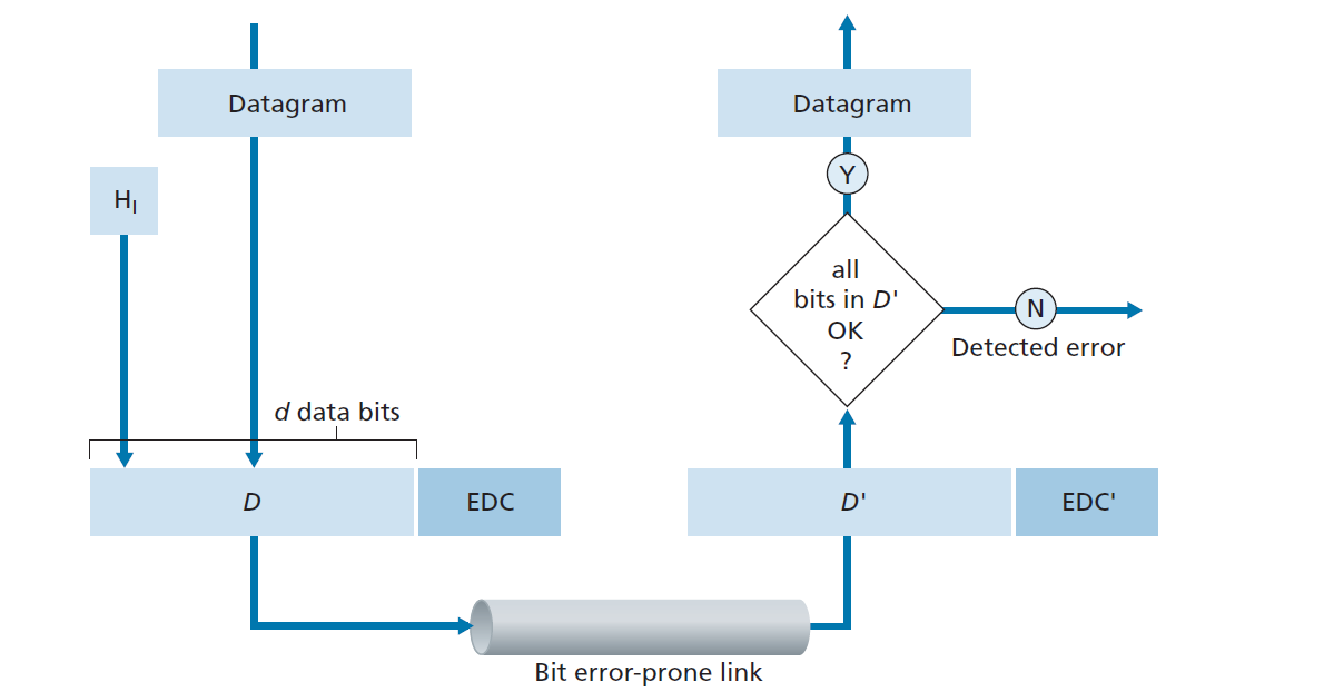
EDC (Error Detection and Correction bits):
- Extra redundant bits added to data to detect and possibly correct errors during transmission.
D (Data):
- The actual data being protected by error checking.
- May include header fields along with the payload.
Important Notes:
- Error detection is not 100% reliable.
- Some errors may go undetected, though this is rare.
- A larger EDC field generally provides:
- Better error detection capability.
- Error detection is not 100% reliable.
Parity Checks
- Even Parity Scheme: the total number of 1s in the $ d + 1 $ bits is even.
- Odd Parity Scheme: the total number of 1s in the $ d + 1 $ bits is odd.
If an odd number of 1-valued bits are found with an even parity schemes, the receiver knows that at least one bit error has occurred.
Two-dimensional Parity
The receiver can thus not only detect the fact that a single bit error has occurred, but can use the column and row indices of the column and row with parity errors to actually identify the bit that was corrupted
and correct that error!

Cyclic Redundancy Check (CRC)
An error-detection technique used widely in today;s computer networks is based on cyclic redundancy check (CRC) codes. CRC codes are also known as polynomial codes, since it is possible to view the bit string to be sent as a polynomial whose coefficients are the $0$ and $1$ values in the bit string, with operations on the bit string interpreted as polynomial arithmetic.
Consider the $d$-bit piece of data, $D$. The sender and receiver must first agree on an $r + 1$ bit pattern, known as a generator, which we will denote as $G$. For a given piece of data, $D$, the sender will choose $r$ additional bits, $R$, and append them to $D$ such that the resulting $d + r$ bit pattern is exactly divisible by $G$.
The process of error checking with CRCs is thus simple: The receiver divides the $d + r$ received bits by $G$. If the remainder is non-zero, the receiver knows that an error has occurred; otherwise the data is accepted as being correct.
How the Sender Computes $R$?
We want find $R$ such that there is an $n$ such that
That is, we want to choose $R$ such that $G$ divides into $D \cdot 2^r \operatorname{XOR} R$ without remainder. If we XOR(that is, add modulo-2, without carry) $R$ to both sides of the above equation, we get
This equation tells us that if we divide $D \cdot 2^r$ by $G$, the value of the remainder is precisely $R$. In other words, we can calculate $R$ as
Summary of the CRC Calculation Process:
- Agree on a generator polynomial $G$ of length $r+1$ bits between sender and receiver.
- Append $r$ zeros to the original $d$-bit data $D$, forming $D \cdot 2^r$.
- Divide $D \cdot 2^r$ by $G$ using modulo-2 division (XOR operation).
- Obtain the remainder $R$ from the division; $R$ is $r$ bits long.
- Append $R$ to the original data $D$ to form the transmitted message.
- At the receiver, divide the received $d+r$ bits by $G$:
- If the remainder is zero, the data is considered correct.
- If not, an error is detected.

Multiple Access Links and Protocols
Two Types of Links
Point-to-Point Links
- Direct connection between two devices.
- Examples:
- PPP (Point-to-Point Protocol) for dial-up access.
- Link between an Ethernet switch and a host.
Broadcast Links
- Shared medium used by multiple devices.
- Examples:
- Old Ethernet (shared coaxial cable).
- Upstream HFC (Hybrid Fiber-Coaxial).
- 802.11 WiFi (wireless LAN).
Multiple Access Protocol
- A single shared broadcast channel is used by multiple nodes.
- If two or more nodes transmit at the same time, their signals interfere, causing a collision.
- A multiple access protocol is needed to coordinate transmissions.
- This protocol is a distributed algorithm that determines when each node can transmit.
- All coordination and communication about channel sharing must occur over the same channel—there is no separate control channel.
Ideal Multiple Access Protocol
- The broadcast channel has a total rate of R bps.
- If only one node transmits, it can use the full rate R.
- If M nodes transmit simultaneously, each gets an average rate of R/M.
- The system is fully decentralized:
- No central coordinator.
- No clock or slot synchronization required.
- The approach is simple and efficient for sharing the channel.
MAC Protocols: a taxonomy
Three Broad Classes of MAC Protocols
Channel Partitioning
- The channel is divided into smaller pieces (such as time slots, frequency bands, or codes).
- Each node is allocated a piece for exclusive use.
Random Access
- The channel is not divided; all nodes can transmit at any time.
- Collisions may occur, but protocols are designed to detect and recover from collisions.
Taking Turns
- Nodes take turns using the channel.
- Nodes with more data to send can take longer turns.
Channel Partitioning Protocols
TDM: time-division multiplexing
FDA: frequency-division multiplexing
CDMA: code division multiple access
TDM (Time-Division Multiplexing)
- Mechanism:
- Divides time into frames, and each frame into $N$ time slots (for $N$ nodes).
- Each node is assigned a specific time slot in each frame.
- When a node has data to send, it transmits only during its assigned slot.
- Example:
- In a four-node TDM system, each node gets one slot per frame, and the slots repeat in a fixed order.
- Advantages:
- No collisions; perfectly fair (each node gets $R/N$ bps).
- Drawbacks:
- Each node is limited to $R/N$ bps even if others are idle.
- Nodes must wait for their turn, even if they are the only one with data to send.
FDM (Frequency-Division Multiplexing)
- Mechanism:
- Divides the total channel bandwidth ($R$ bps) into $N$ frequency bands, each with bandwidth $R/N$.
- Each node is assigned a unique frequency band for exclusive use.
- Example:
- In a four-node FDM system, each node gets a $4$ KHz band out of a total $16$ KHz channel.
- Advantages:
- No collisions; fair bandwidth allocation.
- Drawbacks:
- Each node is limited to R/N bps, even if others are idle (same as TDM).

CDMA (Code Division Multiple Access)
- Mechanism:
- Each node is assigned a unique code.
- Nodes encode their data using their code and transmit simultaneously over the same channel.
- Receivers use the sender’s code to decode the intended message, even in the presence of other transmissions.
- Features:
- Allows multiple nodes to transmit at the same time without collisions, as long as codes are chosen carefully.
- Widely used in wireless and cellular networks due to its anti-jamming properties.
- Note:
- CDMA codes serve a similar role as time slots in TDM and frequency bands in FDM, enabling multiple access to the channel.
Random Access Protocols
- When a node has a packet to send, it transmits at the full channel data rate $R$.
- There is no prior coordination among nodes before transmission.
- If two or more nodes transmit at the same time, a collision occurs.
- A random access MAC protocol defines:
- How to detect collisions.
- How to recover from collisions (e.g., by delaying and retransmitting).
- Examples:
- Slotted ALOHA
- ALOHA
- CSMA, CSMA/CD, CSMA/CA
Slotted ALOHA
Assumptions:
- All frames are the same size.
- Time is divided into equal-sized slots (each slot = time to transmit one frame).
- Nodes can only begin transmission at the start of a slot.
- All nodes are synchronized.
- If two or more nodes transmit in the same slot, a collision occurs and is detected by all.
Operation:
- When a node has a new frame, it transmits in the next available slot.
- If there is no collision, the node can send a new frame in the next slot.
- If a collision occurs, the node retransmits the frame in each subsequent slot with probability $p$ until successful.
Pros of Slotted ALOHA:
- A single active node can continuously transmit at the full channel rate.
- Highly decentralized; only slot synchronization among nodes is needed.
- Simple to implement.
Cons of Slotted ALOHA:
- Collisions can occur, wasting slots.
- Idle slots may occur, reducing efficiency.
- Nodes may detect collisions before a full packet is transmitted.
- Requires clock synchronization among all nodes.
Slotted Aloha efficiency
- Efficiency is defined as the long-run fraction of slots that contain a successful transmission (i.e., exactly one node transmits).
- Suppose there are $N$ nodes, each always has frames to send, and each transmits in a slot with probability $p$.
- The probability that a given node has a successful transmission in a slot:
$p(1-p)^{N-1}$ - The probability that any node has a successful transmission in a slot:
$Np(1-p)^{N-1}$ - Maximum efficiency is achieved by choosing $p^*$ that maximizes $Np(1-p)^{N-1}$.
- As $N$ becomes very large, the maximum efficiency approaches:
$\boxed{1/e \approx 0.37}$ - Interpretation:
At best, the channel is used for successful transmissions only 37% of the time.
Pure (unslotted) ALOHA
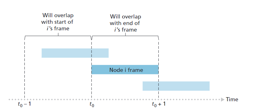
- Simpler than slotted ALOHA; no synchronization required.
- When a frame arrives, the node transmits immediately.
- Higher collision probability:
- A frame sent at time $t_0$ will collide with any other frame sent in the interval $[t_0-1, t_0+1]$.
Pure (Unslotted) ALOHA Efficiency:
- Probability of success for a given node:
- $P(\text{success}) = P(\text{node transmits}) \times P(\text{no other node transmits in } [t_0-1, t_0]) \times P(\text{no other node transmits in } [t_0, t_0+1])$
- $= p \cdot (1-p)^{N-1} \cdot (1-p)^{N-1}$
- $= p \cdot (1-p)^{2(N-1)}$
- Maximum efficiency (choosing optimal $p$ and letting $N \to \infty$):
- $\boxed{1/(2e) \approx 0.18}$
- Interpretation:
At best, the channel is used for successful transmissions only 18% of the time in pure ALOHA.