Computer Networking, A Top-Down Approach, 5th Edition
交换机网络通信原理解析
交换机接口MAC地址的实际用途
交换机每个接口虽有MAC地址,但并非用于普通数据转发,而主要用于: - 管理访问(Telnet/SSH/Web界面登录) - 协议通信(STP生成树协议、LLDP等) - 故障诊断和监控
数据帧如何通过交换机转发
关键误解在于认为数据帧的目标MAC需要是交换机的MAC。实际上:
- 正常帧转发过程:
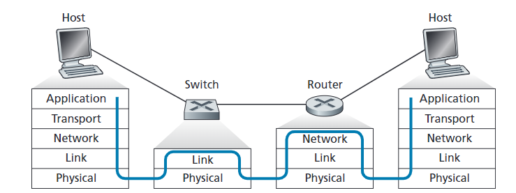
- 主机A发送数据到F时,帧中目标MAC是路由器的MAC(不是交换机)
- 交换机收到帧后不检查“这是否发给我”
- 交换机仅通过MAC地址表查询决定从哪个端口转发出去
- 交换机的核心工作原理:
- 交换机维护一个MAC地址表,记录“哪个MAC地址在哪个端口”
- 收到帧后,查表找到目标MAC对应端口
- 从对应端口转发,不修改帧内容
- 同网段和跨网段通信区别:
- 同网段:源MAC→主机A,目标MAC→主机B
- 跨网段:源MAC→主机A,目标MAC→路由器接口
结论
交换机处理所有收到的有效帧,不会因为目标MAC不是自己而丢弃。这与路由器不同,路由器只处理目标MAC是自己接口MAC的帧。
正是因为交换机不修改MAC地址并且不以自身MAC为转发判断依据,才使得以太网能够高效透明地工作。
Introduction and Service
Some terminology
我们规定:
- Nodes: hosts and routers;
- Links: communication channels that connect adjacent nodes along communication path;
- wired links
- wireless links
- LANs
- layer-2 packet is a frame, encapsulates datagram.
这里就是在说 data link layer 的数据包叫做 frame。
Link layer: context
Datagram transferred by different link protocols over different links, each link protocol provides different services.
不同的 link 用不同的 protocol。
Link Layer Services
- framing, link access
- encapsulate datagram into frame, adding header, trailer.
- channel access if shared medium.
- MAC addresses used in frame headers to identify source, dest.
- reliable delivery between adjacent nodes
- seldom used on low bit-error link (fiber, some twisted pair).
- flow control
- pacing between adjacent sending and receiving nodes.
- error detection
- errors caused by signal attenuation, noise.
- receiver detects presence of errors: signals sender for retransmission or drops frame.
- error correction
- receiver identifies and corrects bit error(s) without resorting to retransmission.
- half-duplex and full-duplex(半双工和全双工)
- with half duplex, nodes at both ends of link can transmit, but not at same time.
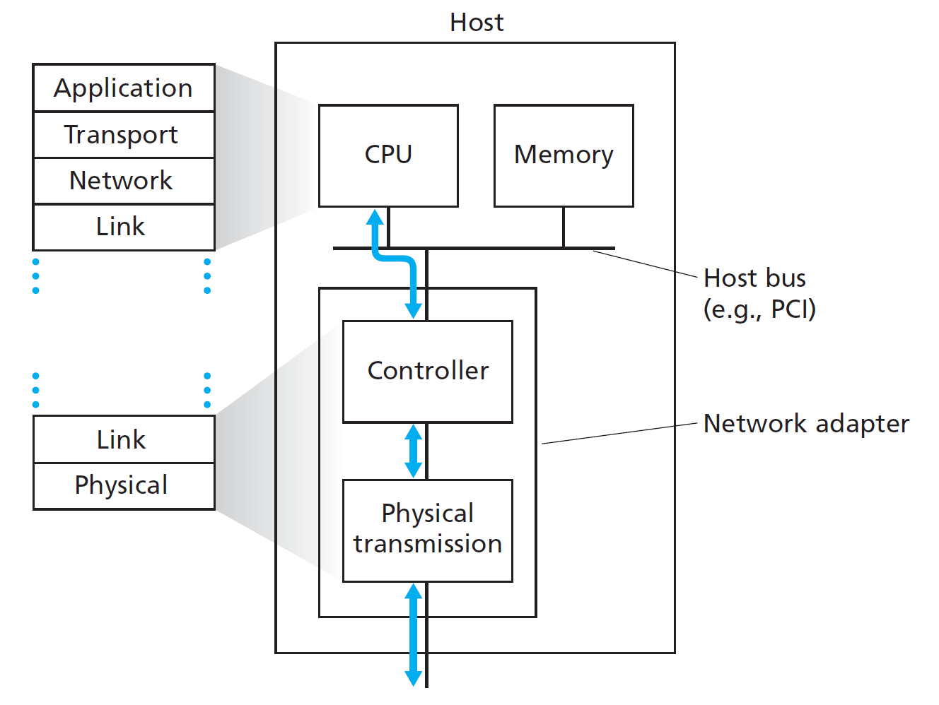
Where is the link layer implemented?
- The link layer is implemented in every host.
- It is realized through an adaptor, also known as a Network Interface Card (NIC).
- Examples include: Ethernet cards, PCMCIA cards, and 802.11 wireless cards.
- The adaptor is responsible for implementing both the link layer and the physical layer.
- It connects to the host via the system buses.
- The adaptor is a combination of hardware, software, and firmware.
In essence, the NIC handles the lower layers of network communication and serves as the interface between the host and the physical network.
Adaptors Communicating
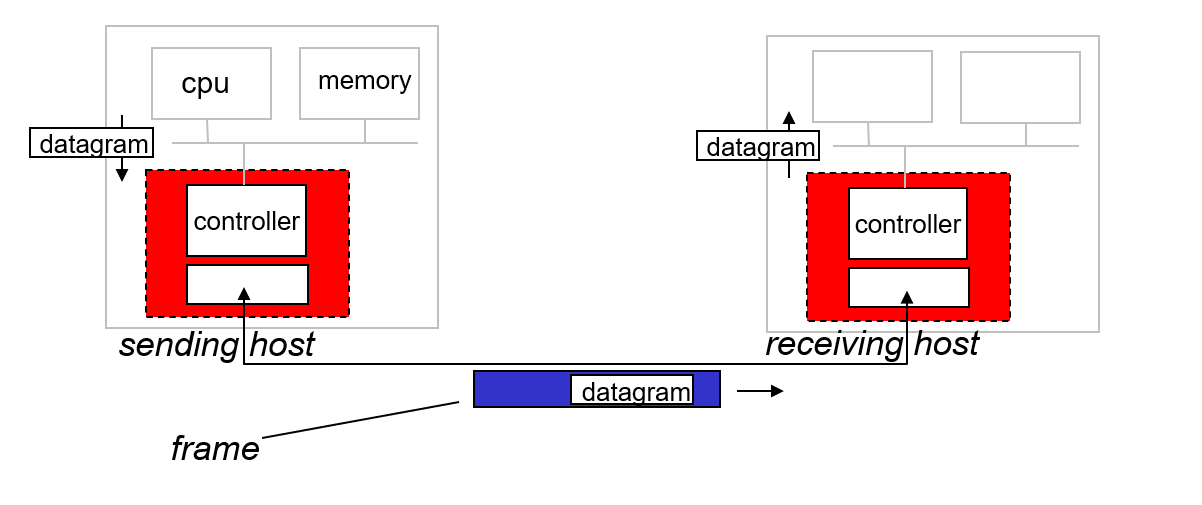
Sending Side
- Encapsulates the network-layer datagram into a link-layer frame.
- Adds:
- Error checking bits (e.g., CRC).
- Reliable data transfer (rdt) mechanisms (if needed).
- Flow control to manage data rate between sender and receiver.
Receiving Side
- Checks the frame for:
- Errors using error detection codes.
- Reliable data transfer mechanisms.
- Flow control compliance.
- Extracts the datagram from the frame.
Error Detection and Correction
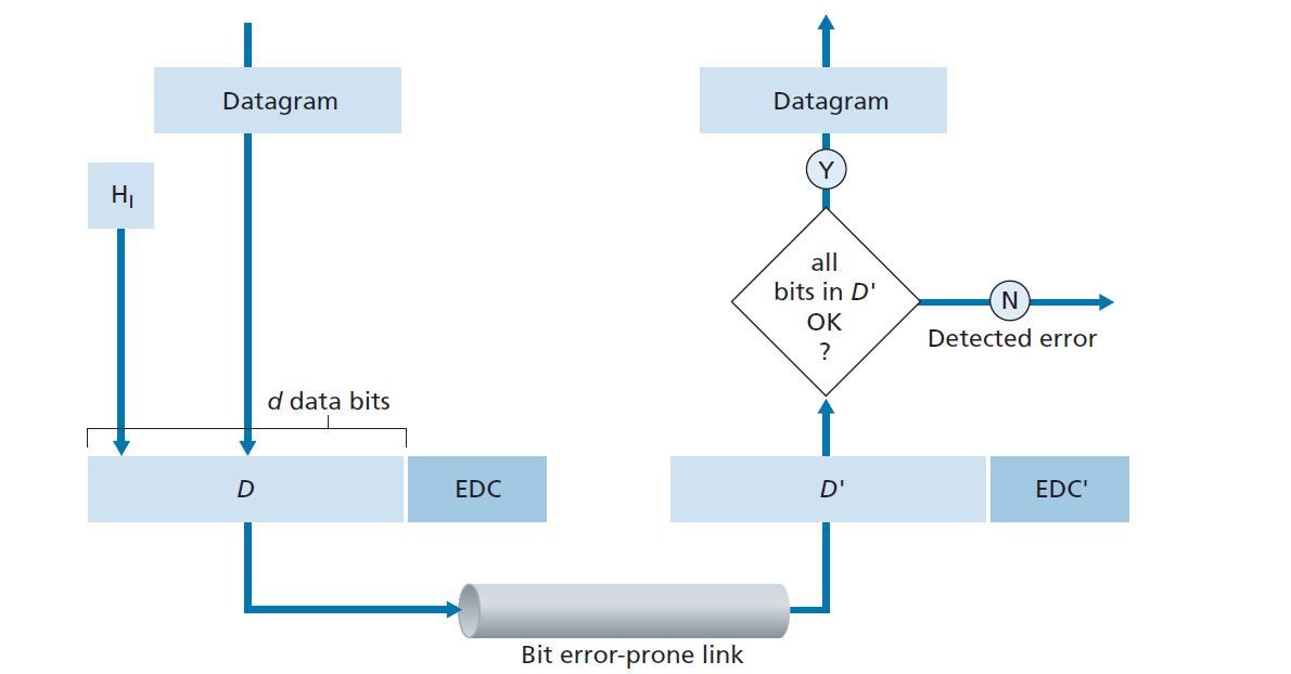
- EDC (Error Detection and Correction bits):
- Extra redundant bits added to data to detect and possibly correct errors during transmission.
- D (Data):
- The actual data being protected by error checking.
- May include header fields along with the payload.
也就是整个 IP datagram。
- Important Notes:
- Error detection is not 100% reliable.
- Some errors may go undetected, though this is rare.
- A larger EDC field generally provides:
- Better error detection capability.
- Error detection is not 100% reliable.
Parity Checks
- Even Parity Scheme: the total number of \(1\)s in the $ d + 1 $ bits is even.
- Odd Parity Scheme: the total number of \(1\)s in the $ d + 1 $ bits is odd.
偶校验和奇校验。
If an odd number of \(1\)-valued bits are found with an even parity schemes, the receiver knows that at least one bit error has occurred.
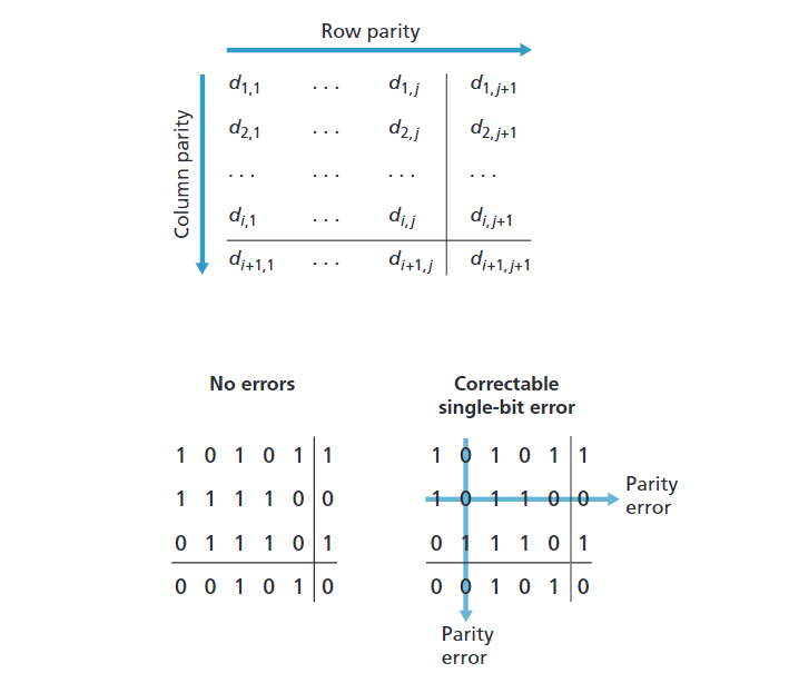
Two-dimensional Parity
The receiver can thus not only detect the fact that a single bit error has occurred, but can use the column and row indices of the column and row with parity errors to actually identify the bit that was corrupted and correct that error!
Cyclic Redundancy Check (CRC)
An error-detection technique used widely in today’s computer networks is based on cyclic redundancy check (CRC) codes. CRC codes are also known as polynomial codes, since it is possible to view the bit string to be sent as a polynomial whose coefficients are the \(0\) and \(1\) values in the bit string, with operations on the bit string interpreted as polynomial arithmetic.
- 数据表示:将要发送的 \(d\) 位数据 \(D\) 看作一个二进制多项式。
- 生成多项式 \(G\):发送方和接收方事先约定一个 \(r + 1\) 位的生成多项式 \(G\)。
- 附加冗余位 \(R\):发送方为 \(D\) 选择 \(r\) 位冗余位 \(R\),并将其附加到 \(D\) 后面,形成 \(d + r\) 位的发送数据,使得整个 \(d + r\) 位数据能被 \(G\) 整除(模 2 运算下)。
How the Sender Computes \(R\)?
简单地来讲:
- 发送方将 \(D\) 左移 \(r\) 位(即在 \(D\) 后面补 \(r\) 个 0),得到 \(D \cdot 2^r\)。
- 用 \(D \cdot 2^r\) 除以 \(G\),得到余数 \(R\)。
- 将 \(R\) 附加到 \(D\) 后面,形成最终发送的数据。
公式表示: \[ R = \operatorname{remainder} \frac{D \cdot 2^r}{G} \]
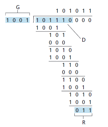
需要注意,\(1 - 0 = 1\),\(0 - 1 = 1\),\(1 - 1 =0\),\(0 - 0 = 0\),没有借位,最后的结果,比如:\(11\),但是 \(r = 3\),则在左侧高位补充 \(0\),也就是 \(R = 011\)。
Multiple Access Links and Protocols
Two Types of Links
Point-to-Point Links
- 定义:点对点链路是指仅有两个设备直接相连的通信链路。
- 典型例子:
- 拨号上网时使用的 PPP(Point-to-Point Protocol)协议。
- 以太网交换机与主机之间的连接。
- 特点:
- 通信双方唯一,链路专用。
- 通常无需考虑信道竞争或冲突问题。
- 实现简单,性能稳定。
Broadcast Links
- 定义:广播链路是指多个设备共享同一个物理通信介质的链路,所有设备都能“听到”同一信道上的数据。
- 典型例子:
- 早期以太网(同轴电缆共享)。
- HFC(Hybrid Fiber-Coaxial)上行链路。
- 802.11 WiFi(无线局域网)。
- 特点:
- 多个节点共享信道,可能发生冲突。
- 需要多路访问协议(如CSMA/CD、ALOHA等)协调各节点的发送时机。
- 支持广播和组播通信。
Multiple Access Protocol
- A single shared broadcast channel is used by multiple nodes.
- If two or more nodes transmit at the same time, their signals interfere, causing a collision.
- A multiple access protocol is needed to coordinate transmissions.
- This protocol is a distributed algorithm that determines when each node can transmit.
- All coordination and communication about channel sharing must occur over the same channel—there is no separate control channel.
多个结点共用一条 channel 进行传输,这条 channel 同一时间只能供一个结点传输。应用 multiple access protocol 来协调。
- 链路(link) 更强调连接关系,即两个节点之间的直接连接。如上文介绍的两种 links。
- 信道(channel) 更强调传输资源,即数据传输所依赖的物理或逻辑媒介。
- 在点对点链路中,link 和 channel 通常是一一对应的。
- 在广播链路中,多个 link(设备间的连接)共享同一个 channel(信道)。
Ideal Multiple Access Protocol
- The broadcast channel has a total rate of \(R\) bps.
- If only one node transmits, it can use the full rate \(R\).
- If \(M\) nodes transmit simultaneously, each gets an average rate of \(R/M\).
- The system is fully decentralized:
- No central coordinator.
- No clock or slot synchronization required.
- The approach is simple and efficient for sharing the channel.
MAC Protocols: a taxonomy
Three Broad Classes of MAC Protocols
- Channel Partitioning
- The channel is divided into smaller pieces (such as time slots, frequency bands, or codes).
- Each node is allocated a piece for exclusive use.
- Random Access
- The channel is not divided; all nodes can transmit at any time.
- Collisions may occur, but protocols are designed to detect and recover from collisions.
- Taking Turns
- Nodes take turns using the channel.
- Nodes with more data to send can take longer turns.
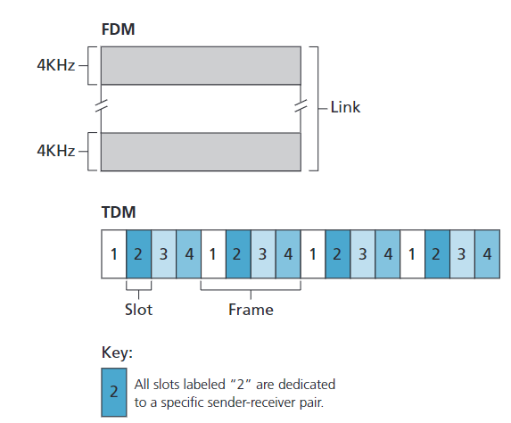
Channel Partitioning Protocols
TDMA: Time Division Multiple Access FDMA: Frequency Division Multiple Access CDMA: Code Division Multiple Access
TDMA
- Mechanism:
- Divides time into frames, and each frame into \(N\) time slots (for \(N\) nodes).
- Each node is assigned a specific time slot in each frame.
- When a node has data to send, it transmits only during its assigned slot.
- Example:
- In a four-node TDMA system, each node gets one slot per frame, and the slots repeat in a fixed order.
- Advantages:
- No collisions; perfectly fair (each node gets \(R/N\) bps).
- Drawbacks:
- Each node is limited to \(R/N\) bps even if others are idle.
- Nodes must wait for their turn, even if they are the only one with data to send.
只能用自己的。
FDMA
- Mechanism:
- Divides the total channel bandwidth (\(R\) bps) into \(N\) frequency bands, each with bandwidth \(R/N\).
- Each node is assigned a unique frequency band for exclusive use.
- Example:
- In a four-node FDM system, each node gets a \(4\) KHz band out of a total \(16\) KHz channel.
- Advantages:
- No collisions; fair bandwidth allocation.
- Drawbacks:
- Each node is limited to R/N bps, even if others are idle (same as TDMA).
CDMA
- Mechanism:
- Each node is assigned a unique code.
- Nodes encode their data using their code and transmit simultaneously over the same channel.
- Receivers use the sender’s code to decode the intended message, even in the presence of other transmissions.
- Features:
- Allows multiple nodes to transmit at the same time without collisions, as long as codes are chosen carefully.
- Widely used in wireless and cellular networks due to its anti-jamming properties.
- Note:
- CDMA codes serve a similar role as time slots in TDMA and frequency bands in FDMA, enabling multiple access to the channel.
每个节点分配一个唯一的编码,所有节点可同时发送,接收端用对应的码提取目标信号。详细过程参考第六章。
Random Access Protocols
- When a node has a packet to send, it transmits at the full channel data rate \(\mathbf{R}\).
- There is no prior coordination among nodes before transmission.(也就是说这个结点传输前不会考虑其它因素)
- If two or more nodes transmit at the same time, a collision occurs.
- A random access MAC protocol defines:(干了两件事)
- How to detect collisions.
- How to recover from collisions (e.g., by delaying and retransmitting).(后传和重传)
- Examples:
- Slotted ALOHA
- ALOHA
- CSMA, CSMA/CD, CSMA/CA
- Slotted ALOHA
Slotted ALOHA
Assumptions: - All frames are the same size. - Time is divided into equal-sized slots (each slot = time to transmit one frame). - Nodes can only begin transmission at the start of a slot. - All nodes are synchronized. - If two or more nodes transmit in the same slot, a collision occurs and is detected by all.
Operation: - When a node has a new frame, it transmits in the next available slot. - If there is no collision, the node can send a new frame in the next slot. - If a collision occurs, the node retransmits the frame in each subsequent slot with probability \(p\) until successful.
Pros of Slotted ALOHA: - A single active node can continuously transmit at the full channel rate. - Highly decentralized; only slot synchronization among nodes is needed. - Simple to implement.
Cons of Slotted ALOHA: - Collisions can occur, wasting slots. - Idle slots may occur, reducing efficiency. - Nodes may detect collisions before a full packet is transmitted. - Requires clock synchronization among all nodes.
前提假设不太现实,要求所有的 frame 大小相同,这样才能确保将时间分为等长的时隙有用。
同步(synchronize) 指的是:
- 所有网络节点共享一个统一的时钟参考
- 每个节点能够准确识别时隙的开始和结束时刻
- 通常通过集中式时钟信号或同步协议实现
Slotted Aloha efficiency
- Efficiency is defined as the long-run fraction of slots that contain a successful transmission (i.e., exactly one node transmits).
- Suppose there are \(N\) nodes, each always has frames to send, and each transmits in a slot with probability \(p\).
- The probability that a given node has a successful transmission in a slot:
\[p(1-p)^{N-1}\] - The probability that any node has a successful transmission in a slot:
\[Np(1-p)^{N-1}\] - Maximum efficiency is achieved by choosing \(p^*\) that maximizes \(Np(1-p)^{N-1}\).
- As \(N\) becomes very large, the maximum efficiency approaches:
\[\boxed{1/e \approx 0.37}\] - Interpretation:
At best, the channel is used for successful transmissions only 37% of the time.
当前时隙有结点传输的概率。
TDMA与Slotted ALOHA对比分析
TDMA和Slotted ALOHA并不矛盾,它们是两种不同设计理念的多址接入协议,尽管都使用了时间分片的概念。
关键区别
| 特性 | TDMA | Slotted ALOHA |
|---|---|---|
| 时隙分配 | 预先固定分配给特定节点 | 动态竞争,任何节点可使用任何时隙 |
| 传输决策 | 只能在自己的专属时隙中传输 | 可以在任何时隙开始传输 |
| 冲突可能性 | 无冲突(每个时隙专属一个节点) | 有冲突(多节点可能同时选择一个时隙) |
| 资源使用 | 节点不传输时其时隙浪费 | 任何节点都可以利用空闲时隙 |
| 控制方式 | 集中式或预先协调 | 分散式(各节点独立决策) |
| 最大效率 | 理论上100%(无冲突) | 理论上约37%(1/e) |
本质区别
- TDMA:预分配固定时隙的“预约”系统
- 类似于餐厅固定座位:每人只能坐自己的座位
- 优点:无冲突,确定性高
- 缺点:资源可能浪费,缺乏灵活性
- Slotted ALOHA:随机竞争时隙的“抢座”系统
- 类似于餐厅先到先得:谁想坐就尝试坐,有冲突就重试
- 优点:简单实现,适应突发流量
- 缺点:存在冲突,效率有限
这两种协议代表了多址接入的两种不同设计思路:静态分配与动态竞争,各有优缺点,适用于不同应用场景。
Pure (unslotted) ALOHA
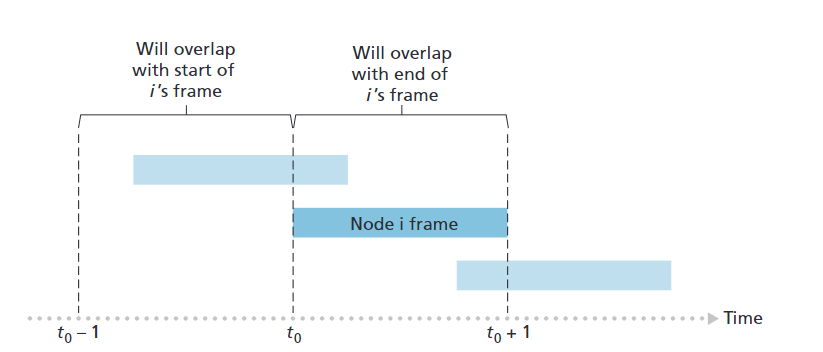
- Simpler than slotted ALOHA; no synchronization required.
- When a frame arrives, the node transmits immediately.
- Higher collision probability:
- A frame sent at time \(t_0\) will collide with any other frame sent in the interval \([t_0-1, t_0+1]\).
Pure (Unslotted) ALOHA Efficiency:
- Probability of success for a given node:
- \(P(\text{success}) = P(\text{node transmits}) \times P(\text{no other node transmits in } [t_0-1, t_0]) \times P(\text{no other node transmits in } [t_0, t_0+1])\)
- \(= p \cdot (1-p)^{N-1} \cdot (1-p)^{N-1}\)
- \(= p \cdot (1-p)^{2(N-1)}\)
- Maximum efficiency (choosing optimal \(p\) and letting \(N \to \infty\)):
- \(\boxed{1/(2e) \approx 0.18}\)
- Interpretation:
At best, the channel is used for successful transmissions only 18% of the time in pure ALOHA.
\(t_0, \, t_0 - 1, \, t_0 + 1\) 三个时隙。
Carrier Sense Multiple Access (CSMA)
发送前先侦听,发送时检测碰撞,以太网核心技术
Carrier Sensing: a node listens to the channel before transmitting. If a frame from another node is currently being transmitted into the channel, a node then waits until it detects no transmissions for a short amount of time and then begins transmission.
In networks using CSMA (like traditional Ethernet or wireless), all nodes communicate over a single shared physical channel. Many network interfaces operating under CSMA protocols are designed for half-duplex communication, meaning they can either transmit OR receive at any given moment, but not both simultaneously. This is why a node can not transmit while receiving.
半双工机制。
CSMA with collision detection (CSMA/CD)
Collision Detection: a transmitting node listens to the channel while it is transmitting. If it detects that another node is transmitting an interfering frame, it stops transmitting and waits a random amount of time before repeating the sense-and-transmit-when-idle cycle.
自己正在传的时候检测到有其他结点开始传了,停止自己的传输,随机等待一段时间后重试。
Taking-Turns Protocols
Polling Protocol
Polling Protocol(轮询协议)是一种轮流访问型的多路访问协议,常用于多个节点共享同一信道的场景。其核心思想是:
- 网络中指定一个节点为主节点(master node)。 - 主节点按照固定顺序依次轮询每个从节点,询问它们是否有数据要发送。 - 只有被轮询到的节点才被允许发送数据。
这个协议有着如下缺陷: 1. 轮询延迟:每个节点都要等主节点轮询到自己才能发送数据,可能会有等待延迟,尤其是节点数量多时。 2. 主节点单点故障:如果主节点出现故障,整个信道就无法正常工作,所有通信都会中断。
Bluetooth protocol
Token-Passing Protocol
A small, special-purpose frame known as a token is exchanged among the nodes in some fixed order.
When a node receives a token, it holds onto the token only if it has some frames to transmit; otherwise, it immediately forwards the token to the next node. If a node does have frames to transmit when it receives the token, it sends up to a maximum number of frames and then forwards the token to the next node.
But it has its problems as well. For example, the failure of one node can crash the entire channel. Or if a node accidentally neglects to release the token, then some recovery procedure must be invoked to get the token back in circulation.
将一个特制的 frame 视作一个 token,这个 token 会在结点中以一个固定的顺序传输,收到 token 的结点可以选择发送自己的 frames 或者立即传给下一个结点。缺陷:时延和崩坏。
fiber distributed data interface (FDDI) protocol
Link-Layer Addressing and ARP
Addressing in Computer Networks
先回顾一下之前学过的 address。
IP Address (32-bit)
- Layer: Network layer address
- Primary function: Used to route datagrams to their destination IP subnet
- Scope: Global addressing for internet-wide routing
MAC Address (48-bit)
- Layer: Data link layer (physical addressing)
- Primary function: Used to transfer frames between directly connected interfaces on the same physical network
- Implementation: Permanently burned into NIC ROM hardware, though sometimes software-configurable
- Scope: Local addressing limited to a single network segment
The fundamental distinction is that IP addresses enable routing across multiple networks, while MAC addresses handle the physical delivery between devices on the same network segment.
- IP 地址:用于在不同网络之间进行路由,确保数据能够跨越多个网络到达最终目标。
- MAC 地址:用于在同一个网络段(如同一个局域网)内实现设备之间的物理交付。
- IP 地址负找路,确定数据应该到哪个网络。
- MAC 地址负责最后一公里,在本地网络中找到具体的设备。
- 路由器转发数据时,每经过一跳,都会用新的 MAC 地址封装数据帧,但 IP 地址保持不变。
假设主机 A 要给主机 B 发送数据:
- 跨网传输:数据包通过多个路由器,依靠 IP 地址进行路由选择。
- 到达目标网络:最后一跳,数据包到达 B 所在的局域网。
- 本地交付:A 通过 ARP 协议获取 B 的 MAC 地址,将数据帧封装后,通过以太网物理传输到 B。
MAC Addresses and ARP
Broadcast address = FF-FF-FF-FF-FF-FF
MAC Address Administration
分配权威(Allocation Authority)
MAC 地址空间由 IEEE(电气和电子工程师协会) 统一管理和分配,确保全球唯一性。分配流程(Assignment Process)
各网络设备制造商需要向 IEEE 购买一批 MAC 地址块。这样,每个厂商生产的设备都能分配到唯一的 MAC 地址,避免地址冲突。结构(Structure)
MAC 地址总长 48 位,前 24 位通常用来标识制造商(称为 OUI,Organizationally Unique Identifier,组织唯一标识符),后 24 位由厂商自行分配给各自的设备。
Conceptual Comparison
- MAC Address: Similar to a Social Security Number
- Permanent identifier tied to hardware
- Remains with the device regardless of location
- IP Address: Similar to a postal address
- Indicates location in the network topology
- Changes when moving between networks
Address Structure Implications
- MAC Address (Flat):
- Provides portability
- LAN card maintains its address when moved between networks
- No inherent network location information
- IP Address (Hierarchical):
- Not portable across networks
- Contains network prefix that identifies subnet
- Must change when moving to a different subnet
- Enables efficient routing across internet
This fundamental difference in addressing philosophy reflects the different purposes of each address type: MAC for unique hardware identification, IP for routable network location.
Address Resolution Protocol (ARP)
The Address Resolution Protocol (ARP) is used to discover the MAC address associated with a known IP address on the same local network:
- Check Local ARP Table First
- Every IP-enabled device maintains an ARP table
- The table contains mappings of IP addresses to MAC addresses
- Each entry format:
<IP address; MAC address; TTL> - TTL (Time To Live): Typically 20 minutes before entry expires
- If MAC Address Not in Table:
- Device broadcasts an ARP request to all devices on LAN
- Uses broadcast MAC address: FF-FF-FF-FF-FF-FF
- The request asks: “Who has IP address B? Send your MAC address”
- Resolution Process:
- Only the device with IP address B responds
- Device B sends its MAC address directly to requester
- Requester adds the IP-to-MAC mapping to its ARP table
- Communication can now proceed using the discovered MAC address
- When Entry Expires:
- After TTL expires, the mapping is removed from ARP table
- A new ARP request must be sent if communication is needed again
ARP is essential because link-layer delivery requires MAC addresses, while applications and higher protocols use IP addresses.
ARP Protocol: Same LAN (Network)
When host A wants to send a datagram to host B on the same local network but doesn’t have B’s MAC address:
ARP Request Process
- Host A broadcasts an ARP query packet containing B’s IP address
- Destination MAC address =
FF-FF-FF-FF-FF-FF(broadcast address) - All machines on the LAN receive the ARP query
- Only host B (with the matching IP address) processes and responds
ARP Response
- Host B replies to A with its (B’s) MAC address
- Frame is sent directly to A’s MAC address (unicast)
- A adds the IP-to-MAC mapping to its ARP table
Caching Mechanism
- A caches (saves) the IP-to-MAC address pair in its ARP table
- Mapping remains until the information becomes old (times out)
- This is “soft state”: information expires unless refreshed through use
Key Characteristics
- Self-configuring: ARP is “plug-and-play”
- Distributed: Nodes create their ARP tables without intervention from network administrators
- Automatic: Mappings are created and maintained dynamically as needed
自己也会创建置换表
Addressing: routing to another LAN
Routing Between Different LANs: Link-Layer Process
When data travels between hosts on different networks, the router plays a critical intermediary role:
Initial Transmission (Source Network)
- Host A creates an IP datagram with:
- Source IP address: Host A’s address
- Destination IP address: Host B’s address (on different LAN)
- Host A determines B is on another network, so packet must go through router R:
- A uses ARP to resolve router interface IP (111.111.111.110) to R’s MAC address
- A creates an Ethernet frame with:
- Destination: R’s MAC address
- Source: A’s MAC address
- Payload: The A-to-B IP datagram
- A’s network interface card transmits this frame onto the LAN
从此可以看出,LAN 内部是通过以太网传输数据的,用的是 MAC address。
Router Processing
Router R’s interface receives the frame (recognizes its MAC address)
R extracts the IP datagram from the frame, examines the IP header:
- Sees destination IP is for host B on another network
- Consults routing table to determine next hop
R prepares to forward to the destination network:
- Uses ARP to resolve B’s IP address to B’s MAC address
- Creates a new Ethernet frame with:
- Destination: B’s MAC address
- Source: R’s MAC address (interface on B’s network)
- Payload: The original A-to-B IP datagram (unchanged)
R 在不同网络段代表不同的路由器接口。
Final Delivery (Destination Network)
Router’s interface on B’s network transmits the new frame
Host B receives the frame, extracts and processes the IP datagram
Note: The IP datagram remains unchanged throughout this process, while the frame addressing changes at each network segment.
Ethernet
The Dominant Wired LAN Technology
- Cost-effective: Extremely affordable - approximately $20 for a Network Interface Card
- Pioneer technology: First widely used LAN technology, establishing the foundation for modern networks
- Simplicity and economy: Significantly simpler and more economical than token LANs and ATM alternatives
- Scalable performance: Successfully kept pace with speed requirements over decades:
- Started at 10 Mbps
- Evolved through 100 Mbps and 1 Gbps
- Now supports up to 10 Gbps and beyond
Ethernet’s combination of low cost, simplicity, and adaptability to increasing performance demands has secured its position as the predominant wired networking technology in local area networks worldwide.
Ethernet Physical Topologies
Historical Evolution
- Bus topology: Popular through mid-1990s
- All nodes connected to a common shared cable
- Single collision domain: All nodes could interfere with each other’s transmissions
- When one node transmitted, all others had to wait
- Limited scalability due to increasing collision probability with more nodes
前面提到过
Modern Configuration
- Star topology: Dominant configuration today
- Central active switch: Intelligent device at center of network
- Point-to-point links between switch and end devices
- Separate collision domains: Each link operates as an independent Ethernet segment
- Nodes connected to different switch ports cannot directly collide with each other
- Dramatically improved performance and reliability compared to bus topology
The shift from bus to star topology represents a fundamental advance in Ethernet technology, effectively eliminating the collision problems that limited earlier implementations.
Ethernet frame structure
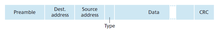
- Preamble:
- 7 bytes with pattern 10101010 followed by one byte with pattern 10101011
- Used to synchronize receiver and sender clock rates
- Allows receivers to “lock onto” the sender’s transmission timing
- Addresses: 6 bytes each
- Destination MAC address (first)
- Source MAC address (second)
- Processing logic:
- If adapter receives frame with matching destination address or broadcast address (FF-FF-FF-FF-FF-FF), it passes data to network layer
- Otherwise, adapter discards the frame
- Broadcast frames (e.g., ARP packets) are processed by all recipients
- Type: 2 bytes
- Indicates the higher layer protocol encapsulated in the frame payload
- Common values:
- 0x0800: IPv4
- 0x0806: ARP
- 0x86DD: IPv6
- Other protocols: Novell IPX, AppleTalk, etc.
- CRC: 4 bytes (32 bits)
- Cyclic Redundancy Check for error detection
- Checked at receiver
- If error is detected, frame is immediately dropped
- No error correction or retransmission at Ethernet level
- Preamble(前导码)是以太网帧结构中的一个字段。
- 由7 个字节的 10101010 模式,后跟1 个字节的 10101011 组成。
- 时钟同步:用于同步接收端和发送端的时钟速率。
- 锁定信号:让接收方能够锁定到发送方的传输时序,确保后续数据能被准确采样和解析。
Ethernet: Key Characteristics
Connectionless Protocol
- No handshaking between transmitting and receiving Network Interface Cards (NICs)
- Each frame is sent independently without establishing a connection first
- Sender simply transmits frames when the medium is available
- No session establishment or termination phases
Unreliable Service
- No acknowledgments (ACKs) or negative acknowledgments (NACKs) sent by receiving NICs
- Sending NIC has no built-in way to know if frames were successfully delivered
- Corrupted frames are simply discarded by the receiver (detected via CRC)
- No automatic retransmission mechanism at the Ethernet level
Implications for Data Delivery
- Stream of datagrams passed to the network layer may contain gaps (missing datagrams)
- If the application uses TCP (Transport layer):
- Gaps will be detected and filled through TCP’s reliable delivery mechanisms
- End users won’t see missing data
- If using UDP or other unreliable protocols:
- Application will see the gaps and must handle them if needed
- Responsibility for reliability shifts to the application layer
Medium Access Control
- Ethernet’s MAC protocol: unslotted CSMA/CD (Carrier Sense Multiple Access with Collision Detection)
- Provides a way to share the communication medium among multiple devices
- Modern switched Ethernet largely eliminates collisions, but the protocol foundation remains
CSMA/CD Algorithm in Ethernet
Ethernet’s original medium access control protocol uses CSMA/CD (Carrier Sense Multiple Access with Collision Detection) to handle shared medium access:
Step-by-Step Process
- Frame Creation
- NIC receives datagram from network layer
- Creates an Ethernet frame with appropriate headers
- Channel Sensing
- If NIC senses channel is idle: begins frame transmission immediately
- If NIC senses channel is busy: waits until channel becomes idle, then transmits
- Successful Transmission
- If NIC transmits the entire frame without detecting another transmission
- Transmission is complete and successful
- Collision Handling
- If NIC detects another transmission while transmitting
- Immediately aborts transmission
- Sends a brief jam signal to ensure all stations recognize the collision
- Exponential Backoff
- After aborting, NIC enters exponential backoff procedure:
- After the mᵗʰ collision, NIC chooses K randomly from {0,1,2,…,2ᵐ-1}
- NIC waits K·512 bit times before attempting retransmission
- Returns to Step 2 to attempt transmission again
The exponential backoff mechanism ensures that after repeated collisions, stations spread their retransmission attempts over increasingly longer intervals, reducing the probability of repeated collisions.
Ethernet’s CSMA/CD: Technical Details
Collision Handling Components
- Jam Signal:
- 48-bit signal transmitted after detecting a collision
- Purpose: Ensures all transmitting stations are aware of the collision
- Small, fixed size makes collision detection efficient
- Contains a deliberate pattern that cannot be mistaken for valid data
- Bit Time:
- The time required to transmit one bit on the network
- For \(10\) Mbps Ethernet: \(0.1\) microseconds per bit
- Used as the basic time unit for backoff calculations
- For \(K = 1023\) (maximum backoff value), wait time is approximately \(50\) milliseconds
Exponential Backoff Algorithm
- Goal: Adaptively adjust retransmission timing based on estimated network load
- Under heavy load conditions, stations wait longer before retrying
- Helps prevent collision cascades when multiple stations are competing for access
- Progressive Backoff Process:
- After first collision: Choose K randomly from \(\{0,1\}\)
- Wait time = \(K × 512\) bit transmission times
- After second collision: Choose K randomly from \(\{0,1,2,3\}\)
- After third collision: Choose K randomly from \(\{0,1,2,3,4,5,6,7\}\)
- Pattern continues: After nth collision, range is \(\{0,1,2,...,2^n-1\}\)
- After tenth collision: Choose K randomly from \(\{0,1,2,...,1023\}\)
- Maximum range is capped at \(\{0,1,2,...,1023\}\) even after more collisions
- After first collision: Choose K randomly from \(\{0,1\}\)
This adaptive algorithm ensures efficient channel utilization by dynamically adjusting to network congestion levels, minimizing repeated collisions while maintaining reasonable access times.
CSMA/CD efficiency
- \(t_{prop}\): max prop delay between \(2\) nodes in LAN;
- \(t_{trans}\): time to transmit max-size frame.
\[ \text{efficiency} = \frac{1}{1 + \frac{5 t_{prop}}{t_{trans}}} \]
Ethernet Standards: Link & Physical Layers
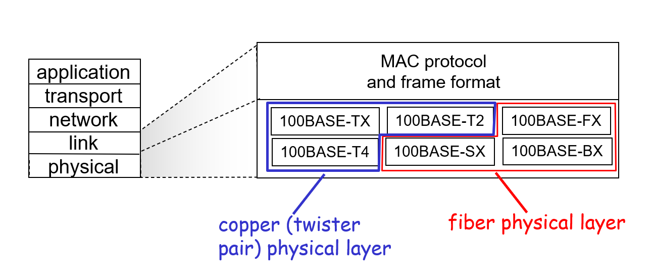
- Common Foundation:
- All Ethernet variants share the same MAC protocol principles
- Frame format remains consistent across implementations
- Upper layers interact with Ethernet through the same interface regardless of physical medium
- Speed Evolution:
- 2 Mbps: Early experimental implementations
- 10 Mbps: Original Ethernet standard (10BASE-T)
- 100 Mbps: Fast Ethernet (100BASE-TX, 100BASE-FX)
- 1 Gbps: Gigabit Ethernet (1000BASE-T, 1000BASE-SX/LX)
- 10 Gbps: 10 Gigabit Ethernet (10GBASE-T, 10GBASE-SR/LR)
- Higher speeds: 40 Gbps, 100 Gbps, 400 Gbps technologies now available
- Physical Media Diversity:
- Copper cable:
- Twisted pair (Cat5e, Cat6, Cat6a, Cat7)
- Coaxial cable (older implementations)
- Optical fiber:
- Multimode fiber (shorter distances)
- Single-mode fiber (longer distances)
- Various wavelengths and transmission techniques
- Copper cable:
This standardized approach allows equipment from different manufacturers to interoperate while enabling continuous performance improvements through new physical layer technologies.
Link-Layer Switches
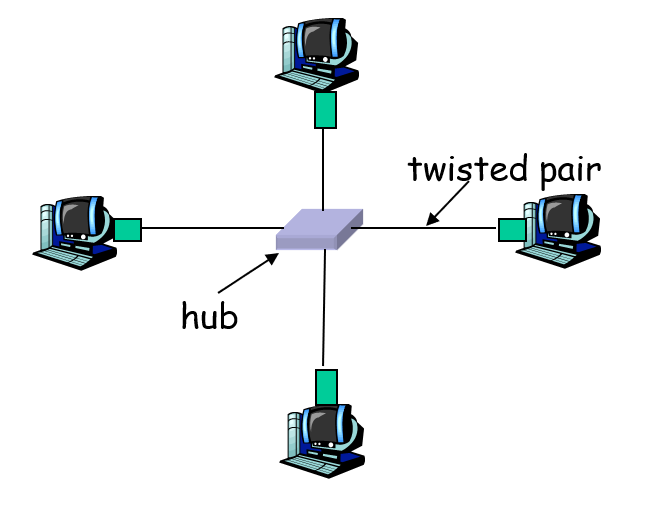
Hubs
physical-layer (dumb) repeaters: - bits coming in one link go out all other links at same rate - all nodes connected to hub can collide with one another - no frame buffering - no CSMA/CD at hub: host NICs detect collisions
Switch
- Link-layer intelligence:
- Smarter than hubs, taking an active role in network traffic management
- Process frames at the data link layer (Layer 2) rather than merely repeating signals
- Make forwarding decisions based on MAC addresses
- Store-and-forward operation:
- Receive complete frames before forwarding
- Buffer frames in memory, allowing for collision domain isolation
- Check frames for errors (using CRC) before forwarding, improving network reliability
- Selective forwarding:
- Examine incoming frame’s destination MAC address
- Forward frame only to the specific port where destination device is connected
- Send to multiple ports only when necessary (broadcasts, unknown destinations)
- When forwarding frames onto a segment, uses CSMA/CD to access the medium
- Transparent operation:
- Hosts are completely unaware of switches’ presence in the network
- End devices communicate as if directly connected
- No modification of frame content during transit through switch
- Plug-and-play functionality:
- Self-learning capability builds forwarding tables automatically
- Observes source MAC addresses of incoming frames to learn device locations
- Dynamically updates tables when devices move to different ports
- No manual configuration required for basic operation
These capabilities allow switches to significantly improve network performance by creating separate collision domains for each port while maintaining the same Ethernet protocol standards.
Switch: Advanced Link-Layer Functionality
- Simultaneous transmissions:
- Allows multiple pairs of nodes to transmit concurrently
- Different ports can carry independent data streams at the same time
- Dramatically increases total network throughput compared to hubs
- Dedicated connections:
- Each host has a dedicated, direct connection to the switch
- Full bandwidth of the link is available to each host-switch connection
- No competition for bandwidth between devices on different ports
- Frame buffering:
- Switches contain memory to store frames temporarily
- Can hold frames when output ports are busy
- Prevents frame loss during periods of network congestion
- Enables handling of traffic between different speed interfaces
- Collision elimination:
- Ethernet protocol used on each link but without collisions
- Full-duplex operation: simultaneous transmission and reception
- Each link is its own separate collision domain
- CSMA/CD no longer needed on point-to-point links to switch
- Parallel communications:
- Host A can transmit to host A’ while host B simultaneously transmits to host B’
- No interference between unrelated data flows
- Example: In a network with hosts A, A’, B, and B’ all connected to a switch:
- A→A’ and B→B’ transmissions occur in parallel
- Network throughput effectively multiplied by number of concurrent transmissions
- Contrast with hubs:
- Hubs force a single shared collision domain among all connected devices
- Only one device can transmit at any given time with a hub
- Switches enable parallel, independent data flows that hubs cannot support
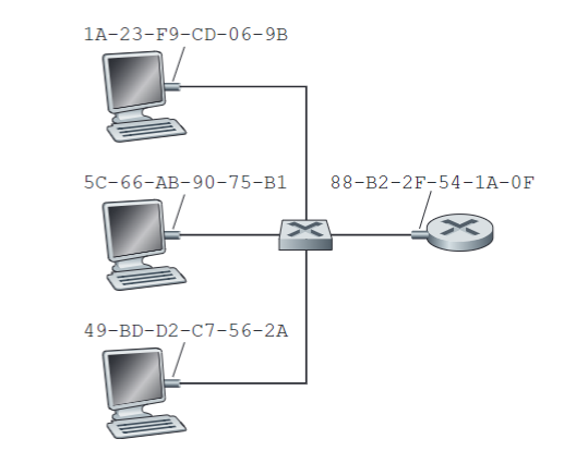
Switch Table
Q: How does switch know that A’ reachable via interface 4, B’ reachable via interface 5?
A: Each switch has a switch table, each entry contains
- MAC address of host
- Interface to reach host
- Time stamp
This structure is similar to a routing table, but operates at Layer 2 (MAC addresses) rather than Layer 3 (IP addresses).
Q: How are entries created, maintained in switch table? Something like a routing protocol?
A: Switch tables are built through self-learning
- Self-learning process:
- Initially the switch table is empty
- When a frame arrives, the switch records the sender’s MAC address and the interface on which it arrived
- The switch learns the location of hosts based on the source MAC address of incoming frames
- Table maintenance:
- Each entry has a time-to-live (typically 20-30 minutes)
- Entries are refreshed when new frames from the same source arrive
- Entries timeout and are removed if not refreshed before TTL expires
- Handling unknown destinations:
- If destination MAC is unknown (not in table), the switch floods the frame to all interfaces except the one it arrived on
- Once the destination host responds, its location is learned
- Key differences from routing protocols:
- No explicit protocol messages exchanged between switches for MAC learning
- Learning is passive, based solely on observing normal traffic
- Completely automatic with no configuration required
Switch: Self-Learning
Learning Host Locations
- Basic principle: Switches automatically learn which hosts are located on which interfaces
- No configuration required: Learning happens dynamically as frames traverse the switch
- Process for each incoming frame:
- Switch examines the source MAC address in the frame header
- Switch records the interface on which the frame arrived
- Switch associates this MAC address with this interface in its table
- Timestamp is recorded for the entry for aging purposes
Switch Table Management
- Dynamic updates: If a host moves to a different port, the switch updates its table when the host transmits
- Aging mechanism: Each entry includes a time-to-live (typically 20-30 minutes)
- Entries are refreshed when new frames from the same source arrive
- If no frames are received from a MAC address before TTL expires, entry is removed
- Adaptation to network changes: Tables automatically adjust when:
- New devices connect to the network
- Existing devices are moved to different switch ports
- Devices are removed from the network
Handling Unknown Destinations
- Initial state: Empty table when switch boots up
- Flooding: When destination is unknown (not in table), switch forwards frame out all interfaces except the arrival interface
- Progressive learning: Table builds up as hosts send frames, gradually reducing the need for flooding
- Self-correcting: If an entry becomes outdated, flooding will occur until the host location is relearned
This passive learning approach enables plug-and-play networking with minimal administrative overhead.
Switch: Frame Filtering/Forwarding
Frame Processing Algorithm
When a frame is received by a switch, it follows this decision process:
- Record source information:
- Record the link/interface associated with the sending host
- Update or create switch table entry for source MAC address
- Destination lookup:
- Index the switch table using the destination MAC address
- Forwarding decision:
- If destination MAC entry is found in table:
- If destination is on same segment from which frame arrived:
- Drop the frame (no need to forward to the same segment)
- Else:
- Forward the frame on the interface indicated in the table entry
- If destination is on same segment from which frame arrived:
- Else (destination not found in table):
- Flood the frame (forward on all interfaces except the one on which it arrived)
- If destination MAC entry is found in table:
- Flooding process:
- When flooding is required, the frame is sent out all switch ports
- Exception: Never send the frame back on the interface where it was received
- This ensures the destination will receive the frame if it exists on the network
- Subsequent replies will help the switch learn the destination’s location
This algorithm combines the efficiency of direct forwarding with the reliability of flooding when necessary, while also preventing unnecessary network traffic through frame filtering.
Switches vs. Routers: Key Differences
Similarities
- Both are store-and-forward devices
- Receive complete packets/frames before processing and forwarding
- Buffer data during processing
Fundamental Differences
| Characteristic | Switches | Routers |
|---|---|---|
| OSI Layer | Link layer (Layer 2) | Network layer (Layer 3) |
| Addressing | Use MAC addresses | Use IP addresses |
| Header Examination | Examine frame headers | Examine packet headers |
| Decision Making | Simple forwarding based on MAC address | Complex routing decisions based on network topology |
Table Management
- Switches:
- Maintain switch tables mapping MAC addresses to interfaces
- Implement self-learning algorithms (passive learning from traffic)
- Use filtering to prevent unnecessary traffic propagation
- Tables built automatically without configuration
- Routers:
- Maintain routing tables mapping network addresses to next hops
- Implement dynamic routing algorithms (RIP, OSPF, BGP, etc.)
- Exchange routing protocol messages with other routers
- Often require explicit configuration
Operational Scope
- Switches: Operate within a single network (broadcast domain)
- Routers: Connect multiple networks and provide inter-network communication
These fundamental differences reflect their different roles in network architecture: switches optimize local traffic flow within networks, while routers enable traffic to traverse between different networks.
Virtual Local Area Networks (VLANs)
802.1Q VLAN Frame Format
- Compares standard 802.1 Ethernet frame with 802.1Q VLAN frame
- 802.1Q frame adds a 2-byte Tag Protocol Identifier (value: 81-00)
- Includes Tag Control Information with 12-bit VLAN ID field and 3-bit priority field
- CRC is recomputed to account for the added header fields
- Allows frames to carry VLAN identification information
VLANs Spanning Multiple Switches
- VLANs can extend across multiple physical switches
- Trunk ports connect switches and carry frames between VLANs
- Frames forwarded between switches must use 802.1Q protocol to maintain VLAN information
- Example shows Electrical Engineering VLAN (ports 1-8) and Computer Science VLAN (ports 9-15) spanning two switches
- Trunk ports ensure proper VLAN segregation across the extended network
Port-based VLAN
- Provides traffic isolation between different port groups
- Supports dynamic membership where port
- s can be reassigned to different VLANs
- Communication between VLANs requires routing, similar to separate physical networks
- VLANs can be defined by port numbers or by MAC addresses of endpoints
- Vendors typically offer combined switch/router devices to facilitate inter-VLAN routing
VLAN Concept Overview
- Defines VLANs as virtual networks created on a single physical infrastructure
- A single physical switch operates as multiple virtual switches
- Logically separates networks (e.g., Electrical Engineering from Computer Science)
- Provides network segmentation without requiring separate physical switches
- Increases network flexibility, security, and management capabilities
End-of-chapter exercises
R.8
Question
How big is the \(\text{MAC}\) address space? The \(\text{IPv4}\) address space? The \(\text{IPv6}\) address space?
Answer
The sizes of the three address spaces are:
MAC Address Space
- Size: \(2^{48}\) possible addresses
- Format: \(48\)-bit addresses, typically represented as six groups of two hexadecimal digits (e.g.,
00:1A:2B:3C:4D:5E)
IPv4 Address Space
- Size: \(2^{32}\) possible addresses
- Format: \(32\)-bit addresses, typically represented as four decimal numbers separated by dots (e.g.,
192.168.1.1)
IPv6 Address Space
- Size: \(2^{128}\) possible addresses
- Format: \(128\)-bit addresses, typically represented as eight groups of four hexadecimal digits separated by colons (e.g.,
2001:0db8:85a3:0000:0000:8a2e:0370:7334)
The IPv6 address space is vastly larger than both MAC and IPv4 address spaces, which was designed to address the IPv4 address exhaustion problem.
P.4
Consider the previous problem, but instead of containing the binary of the numbers 0 through 9 suppose these 10 bytes contain.
Questions and Answers:
- the binary representation of the numbers 1 through 10.
- the ASCII representation of the letters A through J (uppercase).
- the ASCII representation of the letters a through j (lowercase). Compute the Internet checksum for this data.
下面按 16-bit 大端顺序(高字节在前)计算 Internet 校验和(ones’complement sum):
- 每两个字节组成一个 16-bit 字,超出 0xFFFF 时将高位环回加到低位。
- 对所有字求和后取反。
- 数值 1 ~ 10(二进制,字节值 0x01~0x0A)
1 | |
- 大写字母 A ~ J(ASCII 0x41~0x4A)
1 | |
- 小写字母 a ~ j(ASCII 0x61~0x6A)
1 | |
P.11
Suppose four active nodes—nodes A, B, C and D—are competing for access to a channel using slotted ALOHA. Assume each node has an infinite number of packets to send. Each node attempts to transmit in each slot with probability p. The first slot is numbered slot 1, the second slot is numbered slot 2, and so on.
Questions and Answers:
a. What is the probability that node A succeeds for the first time in slot 5?
在单个 slot 中成功的概率:\[P_{\text{succ}} = p (1 - p)^{3}\]
在前 4 个 slot 中都未成功的概率:\[P_{\text{4s}} = \left(1 - P_{\text{succ}}\right)^{4}\]
也就是:\[P(\text{first success in slot 5}) = \bigl[1 - p(1-p)^3\bigr]^4 \times p(1-p)^3.\]
b. What is the probability that some node (either A, B, C or D) succeeds in slot 4?
总共有 \(N = 4\) 个结点,某个结点在 slot4 成功的概率为: \[ P_{\text{succ}} = 4 \cdot p \cdot (1 - p)^{3} \]
c. What is the probability that the first success occurs in slot 3?
第一次成功出现在 slot3 的概率 \[ P = (1-4p(1-p)^3)^2 \cdot 4p(1-p)^3 \]
d. What is the efficiency of this four-node system?
我们需要计算出使得 \(Np(1-p)^{N-1}\) 最大的 \(p\),记原式子为 \(L(p)\),最优解为 \(p^{\ast}\)。对 \(p\) 求偏导: \[ \frac{\partial L(p)}{\partial p} = 4(1 - p)^{3} - 12p(1 - p)^{2} \]
得到 \[ p^{\ast} = 0.25 \]
所以,效率为: \[ \text{efficiency} = 4 \times 0.25 \times 0.75^3 = \frac{27}{64} \]
P.17
Question and Answer:
Recall that with the CSMA/CD protocol, the adapter waits \(K \cdot 512\) bit times after a collision, where \(K\) is drawn randomly. For \(K = 100\), how long does the adapter wait until returning to Step 2 for a \(10\) Mbps Ethernet? For a \(100\) Mbps Ethernet?
等待时间的计算公式为: \[ T = K \cdot 512 \cdot t_{\text{bit}} \]
其中,\(t_{\text{bit}}\) 是比特时间,其计算公式为: \[ t_{\text{bit}} = \frac{1}{\text{传输速率}} \]
分别带入 \(10\) Mbps 和 \(100\) Mbps,解得分别等待时间为 \(5.12\) ms 和 \(0.512\) ms。
P.18
Question and Answer:
Suppose nodes A and B are on the same \(10\) Mbps Ethernet bus, and the propagation delay between the two nodes is \(325\) bit times. Suppose node A begins transmitting a frame and, before it finishes, node B begins transmitting a frame. Can A finish transmitting before it detects that B has transmitted? Why or why not? If the answer is yes, then A incorrectly believes that its frame was successfully transmitted without a collision. Hint: Suppose at time \(t = 0\) bit times, A begins transmitting a frame. In the worst case, A transmits a minimum-sized frame of \(512 + 64\) bit times. So A would finish transmitting the frame at \(t = 512 + 64\) bit times. Thus, the answer is no, if B’s signal reaches A before bit time \(t = 512 + 64\) bits. In the worst case, when does B’s signal reach A?
- 传播延迟计算
- 两节点之间的传播延迟为 \(325\) 比特时间。
- 因此,B 的信号从 B 传播到 A 所需的时间为 \(325\) 比特时间。
- 最小帧传输时间
- A 传输一个最小帧所需的时间为 \(512 + 64 = 576\) 比特时间。
- 碰撞检测条件
- 如果 B 的信号在 A 完成帧传输之前到达 A,则 A 可以检测到碰撞。
- 在最坏情况下,B 在传播延迟的最后一刻(即 \(t = 325\) 比特时间)开始传输。
- B 的信号需要 \(325\) 比特时间到达 A,因此 B 的信号到达 A 的时间为: \[ t_{\text{到达}} = 325 + 325 = 650 \, \text{比特时间} \]
- 结论
- A 在 \(t = 576\) 比特时间完成帧传输,而 B 的信号在 \(t = 650\) 比特时间到达 A。
- 因此,A 无法检测到碰撞,并会错误地认为其帧已成功传输。
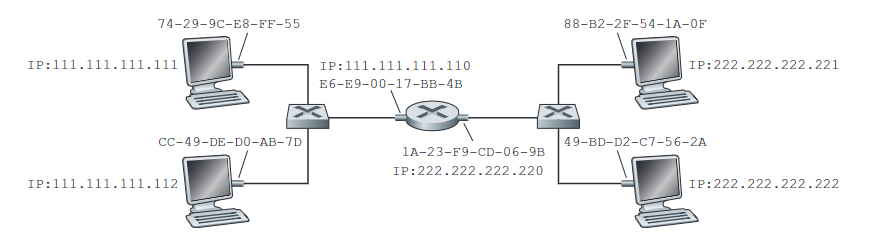
P.27
Question and Answer:
Consider Figure \(5.38\) in problem P\(14\). Provide MAC addresses and IP addresses for the interfaces at Host A, both routers, and Host F. Suppose Host A sends a datagram to Host F. Give the source and destination MAC addresses in the frame encapsulating this IP datagram as the frame is transmitted (i) from A to the left router, (ii) from the left router to the right router, (iii) from the right router to F. Also give the source and destination IP addresses in the IP datagram encapsulated within the frame at each of these points in time.
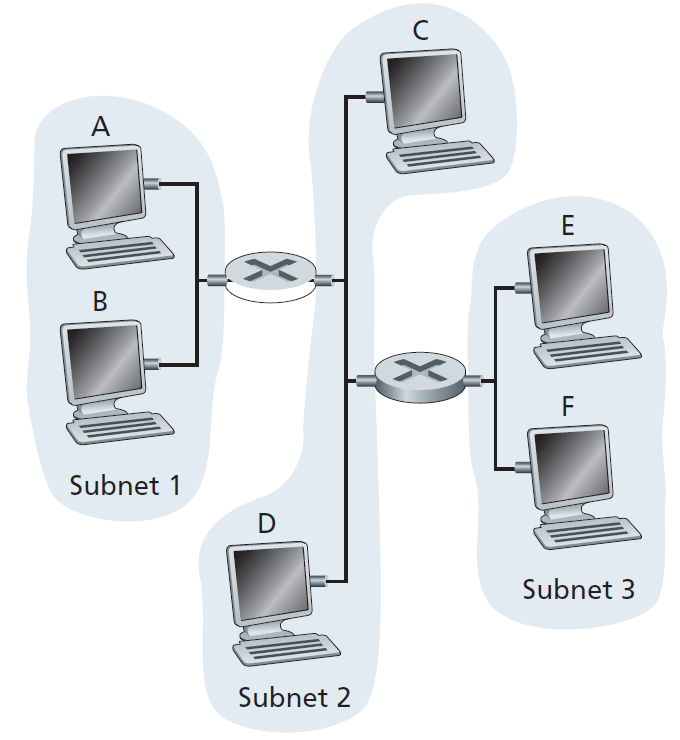
Assign IP addresses to all of the interfaces. For Subnet \(1\) use addresses of the form 192.168.1.xxx; for Subnet \(2\) uses addresses of the form 192.168.2.xxx; and for Subnet \(3\) use addresses of the form 192.168.3.xxx. Assign MAC addresses to all of the adapters.
\(14\) 和 \(27\) 都没有明确说明 IP address 和 MAC address。先分配接口,如下表所示。
| 设备/接口 | 子网 | IP 地址 | MAC 地址 |
|---|---|---|---|
| Host A | Subnet 1 | 192.168.1.1 | AA-AA-AA-AA-AA-AA |
| Host B | Subnet 1 | 192.168.1.2 | BB-BB-BB-BB-BB-BB |
| Router1-接口1 | Subnet 1 | 192.168.1.254 | A1-B1-C1-D1-E1-F1 |
| Router1-接口2 | Subnet 2 | 192.168.2.1 | A1-B2-C2-D2-E2-F2 |
| Router2-接口1 | Subnet 2 | 192.168.2.254 | A2-B1-C1-D1-E1-F1 |
| Router2-接口2 | Subnet 3 | 192.168.3.1 | A2-B2-C2-D2-E2-F2 |
| Host C | Subnet 2 | 192.168.2.2 | CC-CC-CC-CC-CC-CC |
| Host D | Subnet 2 | 192.168.2.3 | DD-DD-DD-DD-DD-DD |
| Host E | Subnet 3 | 192.168.3.2 | EE-EE-EE-EE-EE-EE |
| Host F | Subnet 3 | 192.168.3.3 | FF-FF-FF-FF-FF-FF |
(i) from A to the left router - Source MAC address: AA-AA-AA-AA-AA-AA. - Destination MAC address: A1-B1-C1-D1-E1-F1.
(ii) from the left router to the right router - Source MAC address: A1-B2-C2-D2-E2-F2. - Destination MAC address: A2-B1-C1-D1-E1-F1.
(iii) from the right router to F - Source MAC address: A2-B2-C2-D2-E2-F2. - Destination MAC address: FF-FF-FF-FF-FF-FF.
P.28
Suppose now that the leftmost router in Figure \(5.38\) is replaced by a switch. Hosts A, B, C, and D and the right router are all star-connected into this switch. Give the source and destination MAC addresses in the frame encapsulating this IP datagram as the frame is transmitted (i) from A to the switch, (ii) from the switch to the right router, (iii) from the right router to F. Also give the source and destination IP addresses in the IP datagram encapsulated within the frame at each of these points in time.
首先需要明确的是,switch 的每个接口都有一个 MAC address,但由于 switch 并不会修改经过它的 frame,这里简单地用一个 MAC address 概括。同时,理论上 subnet1 和 subnet2 应该合为一个 subnet,但接下来的结果仍做区分(因为题目要仍在问 MAC address)。
接上题的接口配置,做简单修改:
| 设备/接口 | 子网 | IP 地址 | MAC 地址 |
|---|---|---|---|
| Host A | Subnet 1 | 192.168.1.1 | AA-AA-AA-AA-AA-AA |
| Host B | Subnet 1 | 192.168.1.2 | BB-BB-BB-BB-BB-BB |
| Switch | Subnet 1 2 | 192.168.1.254 | A1-B1-C1-D1-E1-F1 |
| Router2-接口1 | Subnet 2 | 192.168.2.254 | A2-B1-C1-D1-E1-F1 |
| Router2-接口2 | Subnet 3 | 192.168.3.1 | A2-B2-C2-D2-E2-F2 |
| Host C | Subnet 2 | 192.168.2.2 | CC-CC-CC-CC-CC-CC |
| Host D | Subnet 2 | 192.168.2.3 | DD-DD-DD-DD-DD-DD |
| Host E | Subnet 3 | 192.168.3.2 | EE-EE-EE-EE-EE-EE |
| Host F | Subnet 3 | 192.168.3.3 | FF-FF-FF-FF-FF-FF |
(i) from A to the switch - Source MAC address: AA-AA-AA-AA-AA-AA. - Destination MAC address: A2-B1-C1-D1-E1-F1.
(ii) from the switch to the right router - Source MAC address: A1-B1-C1-D1-E1-F1. - Destination MAC address: A2-B1-C1-D1-E1-F1.
(iii) from the right router to F - Source MAC address: A2-B2-C2-D2-E2-F2. - Destination MAC address: FF-FF-FF-FF-FF-FF.
P.32
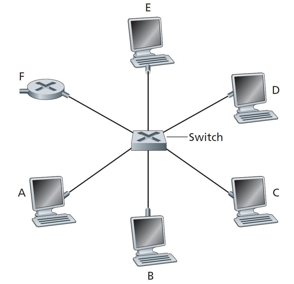
Let’s consider the operation of a learning switch in the context of Figure \(5.24\). Suppose that (i) B sends a frame to E, (ii) E replies with a frame to B, (iii) A sends a frame to B, (iv) B replies with a frame to A. The switch table is initially empty. Show the state of the switch table before and after each of these events. For each of these events, identify the link(s) on which the transmitted frame will be forwarded, and briefly justify your answers.
按字典序从小到大的顺序分配接口,用如下表格总结题目所述过程:
| 步骤 | 事件 | 表项变化 | 转发链路 | 说明 |
|---|---|---|---|---|
| 1 | B→E | +B@2 | 1,3,4,5,6 | 泛洪 |
| 2 | E→B | +E@5 | 2 | 定向转发 |
| 3 | A→B | +A@1 | 2 | 定向转发 |
| 4 | B→A | B@2 刷新 | 1 | 定向转发 |